BC95 Hardware Design NB-IoT Module Series Rev. BC95_Hardware_Design_V1.0 Date: 2016-10-12 www.quectel.
NB-IoT Module Series BC95 Hardware Design Our aim is to provide customers with timely and comprehensive service. For any assistance, please contact our company headquarters: Quectel Wireless Solutions Co., Ltd. Office 501, Building 13, No.99, Tianzhou Road, Shanghai, China, 200233 Tel: +86 21 5108 6236 Email: info@quectel.com Or our local office. For more information, please visit: l e t l c a e i t u n Q ide f n o C http://www.quectel.com/support/salesupport.
NB-IoT Module Series BC95 Hardware Design About the Document History l e t l c a e i t u n Q ide f n o C Revision Date Author Description 1.
NB-IoT Module Series BC95 Hardware Design Contents About the Document ................................................................................................................................... 2 Contents ....................................................................................................................................................... 3 Table Index ....................................................................................................................................
NB-IoT Module Series BC95 Hardware Design 4.5. 4.6. Antenna Requirement ........................................................................................................... 32 RF Cable Soldering ............................................................................................................... 33 5 Electrical, Reliability and Radio Characteristics ............................................................................ 34 5.1. Absolute Maximum Ratings..............................
NB-IoT Module Series BC95 Hardware Design Table Index TABLE 1: FREQUENCY BANDS OF BC95 SERIES MODULE .......................................................................... 9 TABLE 2: BC95 KEY FEATURES ..................................................................................................................... 10 TABLE 3: I/O PARAMETERS DEFINITION ....................................................................................................... 14 TABLE 4: PIN DESCRIPTION ..................
NB-IoT Module Series BC95 Hardware Design Figure Index FIGURE 1: FUNCTIONAL DIAGRAM ................................................................................................................ 11 FIGURE 2: PIN ASSIGNMENT ......................................................................................................................... 13 FIGURE 3: REFERENCE CIRCUIT FOR THE VBAT INPUT ........................................................................... 18 FIGURE 4: TURN-ON TIMING ..........
NB-IoT Module Series BC95 Hardware Design 1 Introduction This document defines the BC95 module and describes its hardware interface which are connected with your application and the air interface. This document can help you quickly understand module interface specifications, electrical and mechanical details. Associated with application note and user guide, you can use BC95 module to design and set up mobile applications easily.
NB-IoT Module Series BC95 Hardware Design 1.1. Safety Information The following safety precautions must be observed during all phases of the operation, such as usage, service or repair of any cellular terminal or mobile incorporating BC95 module. Manufacturers of the cellular terminal should send the following safety information to users and operating personnel, and incorporate these guidelines into all manuals supplied with the product.
NB-IoT Module Series BC95 Hardware Design 2 Product Concept 2.1. General Description l e t l c a e i t u n Q ide f n o C BC95 is a series of NB-IoT module which contains three variants: BC95-CM, BC95-SL and BC95-VF. It is designed to communicate with Mobile Network Operator infrastructure equipment using the NB-IoT radio protocol (3GPP Rel-13). The following table shows the frequency bands of BC95 series module.
NB-IoT Module Series BC95 Hardware Design 2.2. Key Features The following table describes the detailed features of BC95 module. Table 2: BC95 Key Features Feature Implementation Power Supply Supply voltage: 3.1V ~ 4.2V Typical supply voltage: 3.8V Power Saving l e t l c a e i t u n Q ide f n o C Ultra-low sleep current Transmitting Power 23dBm±2dB Temperature Range USIM Interface Support USIM card: 3.
NB-IoT Module Series BC95 Hardware Design 2.3. Functional Diagram The following figure shows a block diagram of BC95 and illustrates the major functional parts. Radio frequency Power management Peripheral interface VBAT l e t l c a e i t u n Q ide f n o C Load Switch APT DCDC Switch TX Filter RF_ANT RF_PA RX_SAW RF Transceiver and Analogue ADC RESET PMU VDD_EXT Baseband Main UART Debug UART Flash SRAM DCDC XTAL Driver USIM SWD SPI NETLIGHT TCXO 38.
NB-IoT Module Series BC95 Hardware Design 3 Application Functions 3.1. General Description l e t l c a e i t u n Q ide f n o C BC95 is equipped with 54-pin 1.1mm pitch SMT pads plus 40-pin ground pads and reserved pads.
NB-IoT Module Series BC95 Hardware Design GND VBAT VBAT RESERVED GND RESERVED RESERVED GND 44 GND 45 GND 46 48 47 49 52 50 53 51 54 RESERVED RF_ANT 3.2.
NB-IoT Module Series BC95 Hardware Design 3.3. Pin Description The following tables show the pin definition and description of BC95. Table 3: I/O Parameters Definition Type Description IO Bidirectional input/output DI l e t l c a e i t u n Q ide f n o C Digital input DO Digital output PI Power input PO Power output AI Analog input AO Analog output OD Open drain Table 4: Pin Description Power Supply Pin Name VBAT Pin No.
NB-IoT Module Series BC95 Hardware Design 59~66, 71~74, 81~83, 92~94 SWD Interface Pin Name Pin No. SWD_ DATA 3 SWD_ CLK 4 Reset Interface Pin Name RESET I/O Description DC Characteristics Comment IO Serial wire data signal VOLmax=0.4V VOHmin=2.4V VILmin=-0.3V VILmax=0.6V VIHmin=2.1V VIHmax=3.3V DI Serial wire clock signal VOLmax=0.4V VOHmin=2.4V I/O Description DC Characteristics Comment Reset the module RPU≈78kΩ VIHmax=3.3V VIHmin=2.1V VILmax=0.6V Pull up internally. Active low.
NB-IoT Module Series BC95 Hardware Design RI 3.0V power domain. If unused, keep this pin open. 34 DO Ring indicator VOLmax=0.4V VOHmin=2.4V Pin No. I/O Description DC Characteristics Comment If unused, keep these pins open. Debug Port Pin Name DBG_ RXD 19 DI Receive data VILmax=0.6V VIHmin=2.1V VIHmax=3.3V DBG_ TXD 20 DO Transmit data VOLmax=0.4V VOHmin=2.4V If unused, keep these pins open. Comment l e t l c a e i t u n Q ide f n o C USIM Interfaces Pin Name Pin No.
NB-IoT Module Series BC95 Hardware Design 35~37, 44, 49, 50, 55~58, 67~70, 75~80, 84~91 3.4. Operating Modes l e t l c a e i t u n Q ide f n o C BC95 module has three operating modes, which can determine availability of functions for different levels of power-saving. Table 5: Overview of Operating Modes Mode Function Active In Active mode, all functions of the module are available and all processors are active. Radio transmission and reception can be performed.
NB-IoT Module Series BC95 Hardware Design The following table shows the VBAT pins and ground pins. Table 6: VBAT and GND Pins Pin Name Pin No. Description Min. Typ. Max. Unit VBAT 45, 46 Power supply for module 3.1 3.8 4.2 V GND 2, 43, 47, 48, 51, 52, 54, 59~66, 71~74, 81~83, 92~94 Ground - 0 - V l e t l c a e i t u n Q ide f n o C 3.5.2. Reference Design for Power Supply The power supply range of the module is 3.1V to 4.2V. Make sure that the input voltage will never drop below 3.
NB-IoT Module Series BC95 Hardware Design 3.6. Power on and down Scenarios 3.6.1. Power on The module can be automatically turned on by supplied power source to VBAT pins. Delay>535us l e t l c a e i t u n Q ide f n o C VBAT RESET Figure 4: Turn-on Timing 3.6.2. Power down The module can be turned off by shutting down the VBAT power supply.
NB-IoT Module Series BC95 Hardware Design 3.6.3. Reset the Module The module can be reset by driving the reset pin to a low level voltage for a certain time. The reset timing is illustrated as the following table. Table 7: Reset Characteristics Pin Name Pin No. Description Reset Time RESET 15 Reset the module, low active >100ms l e t l c a e i t u n Q ide f n o C The recommended circuit is shown as below. You can use open drain/collector driver or button to control the RESET. RESET 4.
NB-IoT Module Series BC95 Hardware Design 3.7. SWD Interface The module provides one Serial Wire Debug (SWD) interface for firmware upgrading. It is recommended to reserve SWD interface in order to upgrade firmware. Table 8: Pin Definition of SWD Interfaces Interfaces SWD SWD Name Pin NO. Description l e t l c a e i t u n Q ide f n o C SWD_DATA 3 Serial wire data signal SWD_CLK 4 Serial wire clock signal The following figure is a reference design for SWD interface.
NB-IoT Module Series BC95 Hardware Design The debug port: DBG_TXD: Send data to the COM port of computer. DBG_RXD: Receive data from the COM port of computer. The logic levels are described in the following table. Table 9: Pin Definition of the UART Interfaces Interfaces Debug Port Main Port Pin No. Pin Name Description Comment l e t l c a e i t u n Q ide f n o C 19 DBG_RXD Receive data 3.0V power domain 20 DBG_TXD Transmit data 3.0V power domain 29 RXD Receive data 3.
NB-IoT Module Series BC95 Hardware Design Module (DCE) PC (DTE) Main port Serial port TXD TXD RXD RXD RING RI GND GND l e t l c a e i t u n Q ide f n o C Figure 9: Reference Design for Main Port 3.8.2. Debug Port Debug port can only be used to capture the system’s log with UE Log View tool and output the log. The baud rate is 921600bps. A reference design for debug port is shown as below.
NB-IoT Module Series BC95 Hardware Design Module Peripheral 1K TXD RXD 1K RXD TXD 1K EINT RI GND GND 10K l e t l c a e i t u n Q ide f n o C Voltage level: 3.3V Figure 11: Level Match Design for 3.3V System NOTE It is highly recommended to add the resistor divider circuit on the UART port signal lines when the host’s voltage level is 3.3V. For systems with a higher voltage level, a level shifter IC could be used between the host and the module.
NB-IoT Module Series BC95 Hardware Design Please visit vendor web site to select the suitable RS-232 level shifter IC, such as: http://www.exar.com/ and http://www.maximintegrated.com. 3.9. ADC Interface* The module provides a 10-bit ADC input channel to measure the value of voltage. This ADC is available in Active mode and Standby mode. l e t l c a e i t u n Q ide f n o C Table 11: Pin Definition of the ADC Name ADC NOTE Pin No.
NB-IoT Module Series BC95 Hardware Design 41 USIM_CLK USIM card clock 40 USIM_DATA USIM card data I/O 39 USIM_RST USIM card reset 42 USIM_GND USIM card ground A reference circuit for 6-pin USIM card connector is illustrated as the following figure.
NB-IoT Module Series BC95 Hardware Design suppress EMI spurious transmission and enhance ESD protection. Please note that the USIM peripheral circuit should be close to the USIM card connector. Place the RF bypass capacitors (33pF) close to the USIM card on all signals lines to improve EMI suppression. 3.11.
NB-IoT Module Series BC95 Hardware Design Table 14: Working State of the NETLIGHT State Module Function Low The module is not working or not synchronized with network. High The module is synchronized with network. A reference circuit is shown as below. VBAT l e t l c a e i t u n Q ide f n o C Module 300R NETLIGHT 4.7K 47K Figure 15: Reference Design for NETLIGHT NOTE “*” means this function is under development.
NB-IoT Module Series BC95 Hardware Design 4 Antenna Interface The pin 53 is the RF antenna pad. The RF interface has an impedance of 50Ω. Table 15: Pin Definition of the RF_ANT Name GND GND RF_ANT GND l e t l c a e i t u n Q ide f n o C Pin Description 51 Ground 52 Ground 53 RF antenna pad 54 Ground 4.1. RF Reference Design A reference design for RF is shown as below. 0R RF_ANT Module NM NM Figure 16: Reference Design for RF BC95 provides an RF antenna pad for antenna connection.
NB-IoT Module Series BC95 Hardware Design 4.1.1. Impedance Control for RF Trace The RF trace in host PCB connected to the module RF antenna pad should be coplanar waveguide line or microstrip line, whose characteristic impedance should be set to 50Ω. It is recommended to use coplanar waveguide line.
NB-IoT Module Series BC95 Hardware Design Figure 19: Layout for Four-layer PCB (Third Layer as Reference Ground) l e t l c a e i t u n Q ide f n o C Figure 20: Layout for Four-layer PCB (Bottom Layer as Reference Ground) 4.2. RF Output Power Table 16: RF Output Power (Uplink GMSK and BPSK Modulation) Frequency 900MHz 850MHz 800MHz NOTE Max. Min. 23dBm±2dB <-40dBm 23dBm±2dB <-40dBm 23dBm±2dB <-40dBm This design is compliant with the NB-IoT radio protocol 3GPP Rel-13.
NB-IoT Module Series BC95 Hardware Design 4.3. RF Receiving Sensitivity Table 17: RF Receiving Sensitivity (MCS-1, BLER <10%) Frequency Receive Sensitivity 900MHz -135dBm 850MHz -135dBm 800MHz l e t l c a e i t u n Q ide f n o C -135dBm 4.4. Operating Frequencies Table 18: Operating Frequencies Frequency 900MHz 850MHz 800MHz Receive Transmit 925~960MHz 880~915MHz 869~894MHz 824~849MHz 791~821MHz 832~862MHz 4.5.
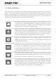
NB-IoT Module Series BC95 Hardware Design Table 20: Antenna Requirements Type Requirements Frequency Range 791-960MHz VSWR ≤2 Gain (dBi) ≥1 Max Input Power (W) 5 Input Impedance (Ω) 50 Polarization Type linear l e t l c a e i t u n Q ide f n o C 4.6. RF Cable Soldering Soldering the RF cable to RF pad of module correctly will reduce the loss on the path of RF, please refer to the following example of RF cable soldering.
NB-IoT Module Series BC95 Hardware Design 5 Electrical, Reliability and Radio Characteristics l e t l c a e i t u n Q ide f n o C 5.1. Absolute Maximum Ratings Absolute maximum ratings for power supply and voltage on digital and analog pins of the module are listed in the following table. Table 21: Absolute Maximum Ratings Parameter Min. Max. Unit -0.3 +4.2 V Peak Current of Power Supply 0 0.3 A RMS Current of Power Supply 0 0.25 A Voltage at Digital Pins -0.3 +3.
NB-IoT Module Series BC95 Hardware Design 5.2. Operating Temperature The operating temperature is listed in the following table: Table 22: Operating Temperature Parameter Min. Typ. Max. Unit Operation Temperature Range 1) -35 +25 +75 ºC l e t l c a e i t u n Q ide f n o C Extended Operation Range 2) NOTES 1. 2. 1) -40 +85 ºC Within operation temperature range, the module is 3GPP compliant.
NB-IoT Module Series BC95 Hardware Design 6 Mechanical Dimensions This chapter describes the mechanical dimensions of the module. l e t l c a e i t u n Q ide f n o C 6.1.
NB-IoT Module Series BC95 Hardware Design l e t l c a e i t u n Q ide f n o C Figure 23: Bottom Dimensions of BC95 Module (Unit: mm) BC95_Hardware_Design Confidential / Released 37 / 45
NB-IoT Module Series BC95 Hardware Design 6.2. Recommended Footprint l e t l c a e i t u n Q ide f n o C Figure 24: Recommended Footprint (Unit: mm) NOTES 1. For easy maintenance of the module, please keep about 3mm between the module and other components in the host PCB. 2. All RESERVED pins must not be connected to GND. 3. All dimensions are in millimeters.
NB-IoT Module Series BC95 Hardware Design 6.3. Design Effect Drawing of the Module l e t l c a e i t u n Q ide f n o C Figure 25: Top View of the Module Figure 26: Bottom View of the Module NOTE These are design effect drawings of BC95 module. For more accurate pictures, please refer to the module that you get from Quectel.
NB-IoT Module Series BC95 Hardware Design 7 Storage and Manufacturing 7.1. Storage l e t l c a e i t u n Q ide f n o C BC95 module is stored in a vacuum-sealed bag. The storage restrictions are shown as below. 1. Shelf life in the vacuum-sealed bag: 12 months at <40ºC/90%RH. 2. After the vacuum-sealed bag is opened, devices that will be subjected to reflow soldering or other high temperature processes must be: Mounted within 72 hours at the factory environment of ≤30ºC/60% RH. Stored at <10% RH.
NB-IoT Module Series BC95 Hardware Design 7.2. Soldering Push the squeegee to apply the solder paste on the surface of stencil, thus making the paste fill the stencil openings and then penetrate to the PCB. The force on the squeegee should be adjusted properly so as to produce a clean stencil surface on a single pass. To ensure the module soldering quality, the thickness of stencil at the hole of the module pads should be 0.15mm. For more details, please refer to document [1].
NB-IoT Module Series BC95 Hardware Design 7.3.1. Tape and Reel Packaging The reel is 330mm in diameter and each reel contains 250 modules.
NB-IoT Module Series BC95 Hardware Design DETAIL:A l e t l c a e i t u n Q ide f n o C 6 PS DETAIL:A Figure 29: Reel Dimensions BC95_Hardware_Design Confidential / Released 43 / 45
NB-IoT Module Series BC95 Hardware Design 8 Appendix A Reference Table 23: Related Documents SN Document Name Remark [1] Module_Secondary_SMT_User_Guide Module Secondary SMT User Guide l e t l c a e i t u n Q ide f n o C Table 24: Terms and Abbreviations Abbreviation ADC DCE DTE I/O IC Imax Inorm kbps LED PCB RF Description Analog-to-Digital Converter Data Communications Equipment (typically module) Data Terminal Equipment (typically computer, external controller) Input/Output Integrated Circ
NB-IoT Module Series BC95 Hardware Design USIM Universal Subscriber Identification Module SMS Short Message Service TE Terminal Equipment TX Transmitting Direction UART Universal Asynchronous Receiver & Transmitter URC Unsolicited Result Code VSWR Vmax Vnorm Vmin VIHmax VIHmin VILmax VILmin VImax VImin VOHmax VOHmin VOLmax VOLmin l e t l c a e i t u n Q ide f n o C Voltage Standing Wave Ratio Maximum Voltage Value Normal Voltage Value Minimum Voltage Value Maximum Input High Level Voltage Va