
Technical data


128 • BACnet/IP Controller 750-830
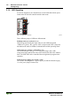
LED Signaling
WAGO-I/O-SYSTEM 750
BACnet/IP Controller
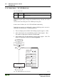
"I/O" LED Error Messages as Blinking Sequences
Error messages are indicated by three consecutive blinking sequences.
1 2 3
Initiation of error indication –Pause– Error code –Pause– Error argument
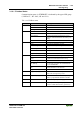
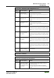
Tab. 3-25: Error messages as blinking sequences – Error codes 1 through 11
Error code 1: "Hardware and configuration error"
Error
argument
Error description Solution
1 Overflow of the inter-
nal buffer memory for
the inline code.
1. Switch off the power for the node.
2. Reduce the number of bus modules
3. Turn on the power supply again.
4. If the error remains, replace the bus coupler.
2 Bus module(s) with
unknown data type
1. Identify the faulty bus module. Turn off the power
supply.
2. Plug the end module into the middle of the node
and switch the power back on.
3. LED continues to flash?
Switch off the power and plug the end module into
the middle of the first half of the node (toward the
controller).
LED not flashing?
Switch off the power and plug the end module into
the middle of the second half of the node (away
from controller).
4. Turn on the power supply again. Repeat this
procedure (while halving the step size) until the
faulty bus module is detected.
5. Replace the faulty bus module. Inquire about a
firmware update for the bus coupler.
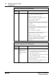
3 Invalid check sum in
the parameter area of
the bus coupler.
1. Switch off the power for the node.
2. Replace the bus coupler and switch the power on
again.
4 Fault when writing in
the serial EEPROM.
1. Switch off power for the node.
2. Replace the bus coupler and switch the power on
again.
5 Fault when reading the
serial EEPROM
1. Switch off power for the node.
2. Replace the bus coupler and switch the power on
again.
6 Changed bus module
configuration found
after AUTORESET.
1. Restart the coupler by turning the supply voltage
off and on again.