
Technical data


BACnet/IP Controller 750-830 • 133
LED Signaling
WAGO-I/O-SYSTEM 750
BACnet/IP Controller
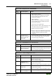
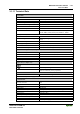
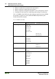
Error code 10 "Error during PLC program processing"
Error
argument
Error description Solution
4 Error while initializing
PFC Web visualization
1. Restart the fieldbus coupler by turning the power
supply off and on again.
2. Should the error persist, perform a reset (origin) in
WAGO-I/O-PRO, retranslate the project again and
reload it to the controller.
5 Error when synchro-
nizing the PLC con-
figuration with the
internal data bus
1. Check the information of the connected modules
in the PLC configuration of WAGO-I/O-PRO
CAA and compare this information with the
modules that are actually connected.
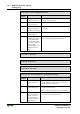
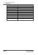
Error code 11 "Gateway/Mailbox module error"
Error
argument
Error description Solution
1 Too many gateway
modules connected
1. Reduce the number of gateway modules
2 Maximum mailbox size
exceeded
1. Reduce the size of the mailbox
3 Maximum PA size
exceeded due to gate-
way modules being
connected.
1. Reduce the data width of the gateway modules
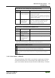
* The number of light pulses (n) indicates the position of the bus module. bus modules
without data are not counted (e.g. supply modules without diagnostics).
Example: The 13th bus module is removed
1. The “I/O” LED starts the error display with the first blinking sequence (approx. 10 Hz).
2. After the first break, the second blinking sequence starts (approx. 1 Hz). The “I/O”
LED blinks four times, indicating error code 4 (data error internal bus).
3. Afterward, the third blinking sequence will start. The I/O LED blinks twelve times.
Error argument 12 means that the internal bus is interrupted behind the twelfth bus
module.
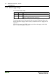
3.1.9.3 Node Status – USR-LED
The bottom indicator LED ("USR") is provided for visual output of informa-
tion about internal bus errors. The activation of the LED from the user pro-
gram occurs with the functions from the WAGO-I/O-PRO library "Visual.lib".