
Technical data

Fieldbus Communication • 165
ETHERNET
WAGO-I/O-SYSTEM 750
BACnet/IP Controller
4.1.2.1 Transmission Media
General ETHERNET transmission standards
For transmitting data the ETHERNET standard supports numerous technolo-
gies with various parameters (e.g., transmission speed, medium, segment
length and type of transmission).
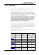
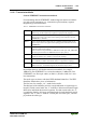
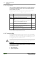
Tab. 4-1: ETHERNET Transmission Standards
1Base5 Uses a 24 AWG UTP (twisted pair cable) for a 1Mbps baseband signal for
distances up to 500 m (250 m per segment) in a physical star topology.
10Base2 Uses a 5 mm 50 Ohm coaxial cable for a 10Mbps baseband signal for dis-
tances of up to 185 m in a physical bus topology (often referred to as Thin
ETHERNET or ThinNet).
10Base5 Uses a 10 mm 50 Ohm coaxial cable for a 10Mbps baseband signal for dis-
tances of up to 500 m in a physical bus topology (often referred to as Thick
ETHERNET).
10BaseF Uses a fiber-optic cable for a 10Mbps baseband signal for distances of up to
4 km in a physical star topology.
(There are three sub-specifications: 10BaseFL for fiber-optic link, 10BaseFB
for fiber-optic backbone and 10BaseFP for fiber-optic passive).
10BaseT Uses a 24 AWG UTP or STP/UTP (twisted pair cable) for a 10Mbps baseband
signal for distances up to 100 m in a physical star topology.
10Broad36 Uses a 75 Ohm coaxial cable for a 10Mbps baseband signal for distances of
up to 1800 m (or 3600 m with double cables) in a physical bus topology.
100BaseTX Specifies a 100 Mbps transmission with a twisted pair cable of Category 5 and
RJ45-connectors. A maximum segment of 100 meters may be used.
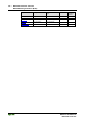
Beyond that there are still further transmission standards, for example:
100BaseT4 (Fast ETHERNET over twisted conductors), 100BaseFX (Fast
ETHERNET over fiber-optic cables) or P802.11 (Wireless LAN) for a wire-
less transmission.
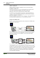
The media types are shown with their IEEE shorthand identifiers. The IEEE
identifiers include three pieces of information.
The first item, for example, “10”, stands for the media.
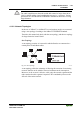
The third part of the identifier provides a rough indication of segment type or
length. For thick coaxial cable, the “5” indicates a 500 meter maximum length
allowed for individual thick coaxial segments. For thin coaxial cable, the “2”
is rounded up from the 185 meter maximum length for individual thin coaxial
segments. The “T” and “F” stand for ‘twisted pair’ and ‘fiber optic’, and sim-
ply indicate the cable type.