
Technical data

Mechanical Setup • 23
Assembly onto Carrier Rail
WAGO-I/O-SYSTEM 750
BACnet/IP Controller
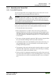
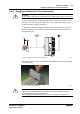
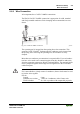
2.6.3 Assembly onto Carrier Rail
2.6.3.1 Carrier Rail Properties
All system components can be snapped directly onto a carrier rail in accor-
dance with the European standard EN 50022 (DIN 35).
Warning
WAGO Kontakttechnik GmbH & Co. KG supplies standardized carrier rails
that are optimal for use with the I/O system. If other carrier rails are used,
then a technical inspection and approval of the rail by WAGO Kontakttech-
nik GmbH & Co. KG should take place.
Carrier rails have different mechanical and electrical properties. For the opti-
mal system setup on a carrier rail, certain guidelines must be observed:
• The material must be non-corrosive.
• Most components have a contact to the carrier rail to ground electro-
magnetic disturbances. In order to avoid corrosion, this tin-plated carrier
rail contact must not form a galvanic cell with the material of the carrier
rail which generates a differential voltage above 0.5 V (saline solution of
0.3% at 20°C) .
• The carrier rail must optimally support the EMC measures integrated into
the system and the shielding of the bus module connections.
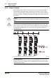
• A sufficiently stable carrier rail should be selected and, if necessary, sev-
eral mounting points (every 20 cm) should be used in order to prevent
bending and twisting (torsion).
• The geometry of the carrier rail must not be altered in order to secure the
safe hold of the components. In particular, when shortening or mounting
the carrier rail, it must not be crushed or bent.
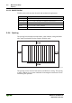
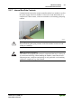
• The base of the I/O components extends into the profile of the carrier rail.
For carrier rails with a height of 7.5 mm, mounting points are to be riveted
under the node in the carrier rail (slotted head captive screws or blind riv-
ets).