
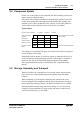
Technical data

Mechanical Setup • 25
Plugging and Removal of the Components
WAGO-I/O-SYSTEM 750
BACnet/IP Controller
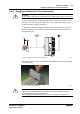
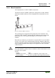
2.6.5 Plugging and Removal of the Components
Warning
Before work is done on the components, the voltage supply must be turned off.
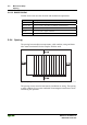
In order to safeguard the coupler/controller from jamming, it should be fixed
onto the carrier rail with the locking disc To do so, push on the upper groove
of the locking disc using a screwdriver.
To pull out the field bus coupler/controller, release the locking disc by press-
ing on the bottom groove with a screwdriver and then pulling the orange col-
ored unlocking lug .
Fig. 2-5: Coupler/Controller and unlocking lug g01xx12e
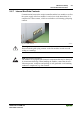
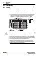
It is also possible to release an individual I/O module from the unit by pulling
an unlocking lug.
Fig. 2-6: removing bus terminal p0xxx01x
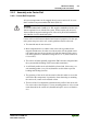
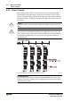
Danger
Ensure that an interruption of the PE will not result in a condition which
could endanger a person or equipment!
For planning the ring feeding of the ground wire, please see chapter 2.6.3.