
Technical data

254 • I/O Modules
Process Data Architecture for MODBUS/TCP
WAGO-I/O-SYSTEM 750
BACnet/IP Controller
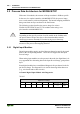
5.2 Process Data Architecture for MODBUS/TCP
With some I/O modules, the structure of the process data is fieldbus specific.
In the case of a coupler/controller with MODBUS/TCP, the process image
uses a word structure (with word alignment). The internal mapping method for
data greater than one byte conforms to the Intel format.
The following section describes the process image for various
WAGO-I/O-SYSTEM 750 and 753 I/O modules when using a cou-
pler/controller with MODBUS/TCP.
Note
Depending on the specific position of an I/O module in the fieldbus node,
the process data of all previous byte or bit-oriented modules must be
taken into account to determine its location in the process data map.
For the PFC process image of the programmable fieldbus controller is the
structure of the process data mapping identical.
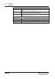
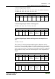
5.2.1 Digital Input Modules
Digital input modules supply one bit of data per channel to specify the signal
state for the corresponding channel. These bits are mapped into the Input
Process Image.
When analog input modules are also present in the node, the digital data is al-
ways appended after the analog data in the Input Process Image, grouped into
bytes.
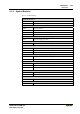
Some digital modules have an additional diagnostic bit per channel in the In-
put Process Image. The diagnostic bit is used for detecting faults that occur
(e.g., wire breaks and/or short circuits).
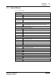
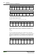
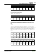
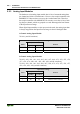
1 Channel Digital Input Module with Diagnostics
750-435
Input Process Image
Bit 7 Bit 6 Bit 5 Bit 4 Bit 3 Bit 2 Bit 1 Bit 0
Diagnostic bit
S 1
Data bit
DI 1