
Technical data

I/O Modules • 255
Process Data Architecture for MODBUS/TCP
WAGO-I/O-SYSTEM 750
BACnet/IP Controller
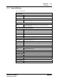
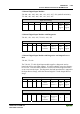
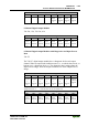
2 Channel Digital Input Modules
750-400, -401, -405, -406, -410, -411, -412, -427, -438, (and all variations),
753-400, -401, -405, -406, -410, -411, -412, -427
Input Process Image
Bit 7 Bit 6 Bit 5 Bit 4 Bit 3 Bit 2 Bit 1 Bit 0
Data bit
DI 2
Channel
2
Data bit
DI 1
Channel
1
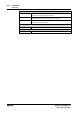
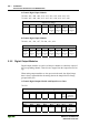
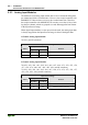
2 Channel Digital Input Modules with Diagnostics
750-419, -421, -424, -425, 753-421, -424, -425
Input Process Image
Bit 7 Bit 6 Bit 5 Bit 4 Bit 3 Bit 2 Bit 1 Bit 0
Diagnostic
bit S 2
Channel 2
Diagnostic
bit S 1
Channel 1
Data bit
DI 2
Channel
2
Data bit
DI 1
Channel
1
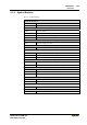
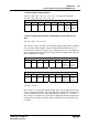
2 Channel Digital Input Module with Diagnostics and Output Process
Data
750-418, 753-418
The 750-418, 753-418 digital input module supplies a diagnostic and ac-
knowledge bit for each input channel. If a fault condition occurs, the diagnos-
tic bit is set. After the fault condition is cleared, an acknowledge bit must be
set to re-activate the input. The diagnostic data and input data bit is mapped in
the Input Process Image, while the acknowledge bit is in the Output Process
Image.
Input Process Image
Bit 7 Bit 6 Bit 5 Bit 4 Bit 3 Bit 2 Bit 1 Bit 0
Diagnostic
bit S 2
Channel 2
Diagnostic
bit S 1
Channel 1
Data bit
DI 2
Channel
2
Data bit
DI 1
Channel
1
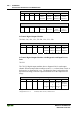
Output Process Image
Bit 7 Bit 6 Bit 5 Bit 4 Bit 3 Bit 2 Bit 1 Bit 0
Acknowl-
edgement bit
Q 2
Channel 2
Acknowl-
edgement bit
Q 1
Channel 1
0 0