
Technical data

256 • I/O Modules
Process Data Architecture for MODBUS/TCP
WAGO-I/O-SYSTEM 750
BACnet/IP Controller
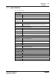
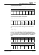
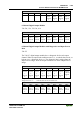
4 Channel Digital Input Modules
750-402, -403, -408, -409, -414, -415, -422, -423, -428, -432, -433,
753-402, -403, -408, -409, -415, -422, -423, -428, -432, -433, -440
Input Process Image
Bit 7 Bit 6 Bit 5 Bit 4 Bit 3 Bit 2 Bit 1 Bit 0
Data bit
DI 4
Channel
4
Data bit
DI 3
Channel
3
Data bit
DI 2
Channel
2
Data bit
DI 1
Channel
1
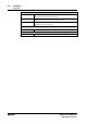
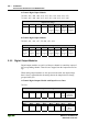
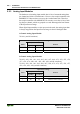
8 Channel Digital Input Modules
750-430, -431, -436, -437, 753-430, -431, -434
Input Process Image
Bit 7 Bit 6 Bit 5 Bit 4 Bit 3 Bit 2 Bit 1 Bit 0
Data bit
DI 8
Channel
8
Data bit
DI 7
Channel
7
Data bit
DI 6
Channel
6
Data bit
DI 5
Channel
5
Data bit
DI 4
Channel
4
Data bit
DI 3
Channel
3
Data bit
DI 2
Channel
2
Data bit
DI 1
Channel
1
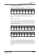
5.2.2 Digital Output Modules
Digital output modules use one bit of data per channel to control the output of
the corresponding channel. These bits are mapped into the Output Process Im-
age.
When analog output modules are also present in the node, the digital image
data is always appended after the analog data in the Output Process Image,
grouped into bytes.
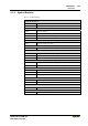
1 Channel Digital Output Module with Input Process Data
750-523
Input Process Image
Bit 7 Bit 6 Bit 5 Bit 4 Bit 3 Bit 2 Bit 1 Bit 0
not
used
Status bit
„Manual
Operation“
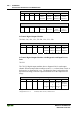
Output Process Image
Bit 7 Bit 6 Bit 5 Bit 4 Bit 3 Bit 2 Bit 1 Bit 0
not
used
controls
DO 1
Channel 1