
Technical data

I/O Modules • 257
Process Data Architecture for MODBUS/TCP
WAGO-I/O-SYSTEM 750
BACnet/IP Controller
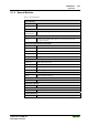
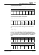
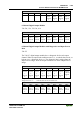
2 Channel Digital Output Modules
750-501, -502, -509, -512, -513, -514, -517, -535, (and all variations),
753-501, -502, -509, -512, -513, -514, -517
Output Process Image
Bit 7 Bit 6 Bit 5 Bit 4 Bit 3 Bit 2 Bit 1 Bit 0
controls
DO 2
Channel
2
controls
DO 1
Channel
1
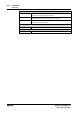
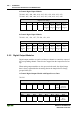
2 Channel Digital Input Modules with Diagnostics and Input Process
Data
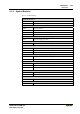
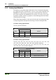
750-507 (-508), -522, 753-507
The 750-507 (-508), -522 and 753-507 digital output modules have a diagnos-
tic bit for each output channel. When an output fault condition occurs (i.e.,
overload, short circuit, or broken wire), a diagnostic bit is set. The diagnostic
data is mapped into the Input Process Image, while the output control bits are
in the Output Process Image.
Input Process Image
Bit 7 Bit 6 Bit 5 Bit 4 Bit 3 Bit 2 Bit 1 Bit 0
Diagnostic
bit S 2
Channel 2
Diagnostic
bit S 1
Channel 1
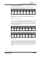
Output Process Image
Bit 7 Bit 6 Bit 5 Bit 4 Bit 3 Bit 2 Bit 1 Bit 0
controls
DO 2
Channel 2
controls
DO 1
Channel 1
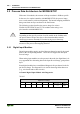
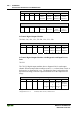
750-506, 753-506
The 750-506, 753-506 digital output module has 2-bits of diagnostic informa-
tion for each output channel. The 2-bit diagnostic information can then be de-
coded to determine the exact fault condition of the module (i.e., overload, a
short circuit, or a broken wire). The 4-bits of diagnostic data are mapped into
the Input Process Image, while the output control bits are in the Output Proc-
ess Image.