
Technical data

I/O Modules • 259
Process Data Architecture for MODBUS/TCP
WAGO-I/O-SYSTEM 750
BACnet/IP Controller
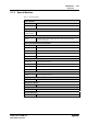
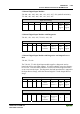
Output Process Image
Bit 7 Bit 6 Bit 5 Bit 4 Bit 3 Bit 2 Bit 1 Bit 0
controls
DO 4
Channel
4
controls
DO 3
Channel
3
controls
DO 2
Channel
2
controls
DO 1
Channel
1
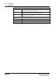
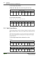
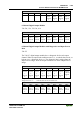
8 Channel Digital Output Module
750-530, -536, 753-530, -434
Output Process Image
Bit 7 Bit 6 Bit 5 Bit 4 Bit 3 Bit 2 Bit 1 Bit 0
controls
DO 8
Channel
8
controls
DO 7
Channel
7
controls
DO 6
Channel
6
controls
DO 5
Channel
5
controls
DO 4
Channel
4
controls
DO 3
Channel
3
controls
DO 2
Channel
2
controls
DO 1
Channel
1
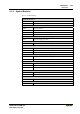
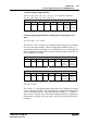
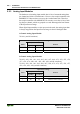
8 Channel Digital Output Modules with Diagnostics and Input Process
Data
750-537
The 750-537 digital output modules have a diagnostic bit for each output
channel. When an output fault condition occurs (i.e., overload, short circuit, or
broken wire), a diagnostic bit is set. The diagnostic data is mapped into the
Input Process Image, while the output control bits are in the Output Process
Image.
Input Process Image
Bit 7 Bit 6 Bit 5 Bit 4 Bit 3 Bit 2 Bit 1 Bit 0
Diagnos-
tic bit S
7
Channel
8
Diagnos-
tic bit S
6
Channel
7
Diagnos-
tic bit S
5
Channel
6
Diagnos-
tic bit S
4
Channel
5
Diagnos-
tic bit S
3
Channel
4
Diagnos-
tic bit S
2
Channel
3
Diagnos-
tic bit S
1
Channel
2
Diagnos-
tic bit S 0
Channel
1
Diagnostic bit S = '0' no Error
Diagnostic bit S = '1' overload, short circuit, or broken wire
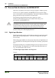
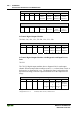
Output Process Image
Bit 7 Bit 6 Bit 5 Bit 4 Bit 3 Bit 2 Bit 1 Bit 0
controls
DO 8
Channel
8
controls
DO 7
Channel
7
controls
DO 6
Channel
6
controls
DO 5
Channel
5
controls
DO 4
Channel
4
controls
DO 3
Channel
3
controls
DO 2
Channel
2
controls
DO 1
Channel
1