
Technical data

I/O Modules • 261
Process Data Architecture for MODBUS/TCP
WAGO-I/O-SYSTEM 750
BACnet/IP Controller
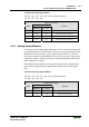
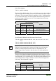
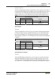
4 Channel Analog Input Modules
750-453, -455, -457, -459, -460, -468, (and all variations),
753-453, -455, -457, -459
Input Process Image
Byte Destination
Offset
High Byte Low Byte
Remark
0 D1 D0 Measured Value Channel 1
1 D3 D2 Measured Value Channel 2
2 D5 D4 Measured Value Channel 3
3 D7 D6 Measured Value Channel 4
5.2.4 Analog Output Modules
The hardware of an analog output module has 16 bits of measured analog data
per channel and 8 bits of control/status. However, the coupler/controller with
MODBUS/TCP does not have access to the 8 control/status bits. Therefore,
the coupler/controller with MODBUS/TCP can only access the 16 bits of ana-
log data per channel, which are grouped as words and mapped in Intel format
in the Output Process Image.
When digital output modules are also present in the node, the analog output
data is always mapped into the Output Process Image in front of the digital
data.
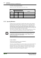
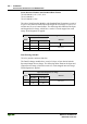
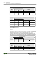
2 Channel Analog Output Modules
750-550, -552, -554, -556, -560, -585, (and all variations),
753-550, -552, -554, -556
Output Process Image
Byte Destination
Offset
High Byte Low Byte
Remark
0 D1 D0 Output Value Channel 1
1 D3 D2 Output Value Channel 2