
Technical data

262 • I/O Modules
Process Data Architecture for MODBUS/TCP
WAGO-I/O-SYSTEM 750
BACnet/IP Controller
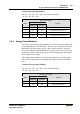
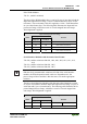
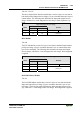
4 Channel Analog Output Modules
750-553, -555, -557, -559, 753-553, -555, -557, -559
Output Process Image
Byte Destination
Offset
High Byte Low Byte
Remark
0 D1 D0 Output Value Channel 1
1 D3 D2 Output Value Channel 2
2 D5 D4 Output Value Channel 3
3 D7 D6 Output Value Channel 4
5.2.5 Specialty Modules
WAGO has a host of Specialty I/O modules that perform various functions.
With individual modules beside the data bytes also the control/status byte is
mapped in the process image. The control/status byte is required for the bi-
directional data exchange of the module with the higher-ranking control sys-
tem. The control byte is transmitted from the control system to the module and
the status byte from the module to the control system.
This allows, for example, setting of a counter with the control byte or display-
ing of overshooting or undershooting of the range with the status byte.
Further information
For detailed information about the structure of a particular module’s con-
trol/status byte, please refer to that module’s manual. Manuals for each
module can be found on the Internet under:
http://www.wago.com.
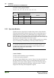
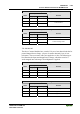
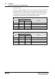
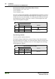
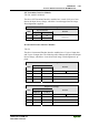
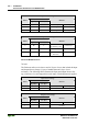
Counter Modules
750-404, (and all variations except of /000-005),
753-404, (and variation /000-003)
The above Counter Modules have a total of 5 bytes of user data in both the In-
put and Output Process Image (4 bytes of counter data and 1 byte of con-
trol/status). The counter value is supplied as 32 bits. The following tables il-
lustrate the Input and Output Process Image, which has a total of 3 words
mapped into each image. Word alignment is applied.