
Technical data

264 • I/O Modules
Process Data Architecture for MODBUS/TCP
WAGO-I/O-SYSTEM 750
BACnet/IP Controller
750-638, 753-638
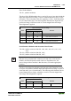
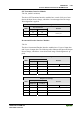
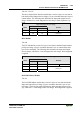
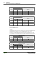
The above Counter Modules have a total of 6 bytes of user data in both the In-
put and Output Process Image (4 bytes of counter data and 2 bytes of con-
trol/status). The two counter values are supplied as 16 bits. The following ta-
bles illustrate the Input and Output Process Image, which has a total of 4
words mapped into each image. Word alignment is applied.
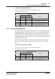
Input Process Image
Byte Destination
Offset
High Byte Low Byte
Remark
0 - S0 Status byte of Counter 1
1 D1 D0 Counter Value of Counter 1
2 - S1 Status byte of Counter 2
3 D3 D2 Counter Value of Counter 2
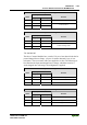
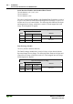
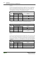
Output Process Image
Byte Destination
Offset
High Byte Low Byte
Remark
0 - C0 Control byte of Counter 1
1 D1 D0 Counter Setting Value of Counter 1
2 - C1 Control byte of Counter 2
3 D3 D2 Counter Setting Value of Counter 2