
Technical data

I/O Modules • 265
Process Data Architecture for MODBUS/TCP
WAGO-I/O-SYSTEM 750
BACnet/IP Controller
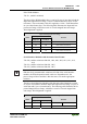
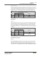
Pulse Width Modules
750-511, (and all variations)
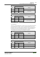
The above Pulse Width modules have a total of 6 bytes of user data in both the
Input and Output Process Image (4 bytes of channel data and 2 bytes of con-
trol/status). The two channel values are supplied as 16 bits. Each channel has
its own control/status byte. The following table illustrates the Input and Out-
put Process Image, which has a total of 4 words mapped into each image.
Word alignment is applied.
Input and Output Process Image
Byte Destination
Offset
High Byte Low Byte
Remark
0 - C0/S0 Control/Status byte of Channel 1
1 D1 D0 Data Value of Channel 1
2 - C1/S1 Control/Status byte of Channel 2
3 D3 D2 Data Value of Channel 2
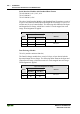
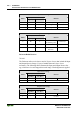
Serial Interface Modules with alternative Data Format
750-650, (and the variations /000-002, -004, -006, -009, -010, -011, -012,
-013)
750-651, (and the variations /000-002, -003)
750-653, (and the variations /000-002, -007)
Note
With the freely parametrizable variations /003 000 of the serial interface
modules, the desired operation mode can be set. Dependent on it, the
process image of these modules is then the same, as from the appropriate
variation.
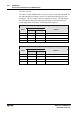
The above Serial Interface Modules with alternative data format have a total
of 4 bytes of user data in both the Input and Output Process Image (3 bytes of
serial data and 1 byte of control/status). The following table illustrates the In-
put and Output Process Image, which have a total of 2 words mapped into
each image. Word alignment is applied.
Input and Output Process Image
Byte Destination
Offset
High Byte Low Byte
Remark
0 D0 C/S Data byte Control/Status byte
1 D2 D1 Data bytes