
Technical data

268 • I/O Modules
Process Data Architecture for MODBUS/TCP
WAGO-I/O-SYSTEM 750
BACnet/IP Controller
750-634
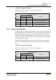
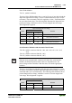
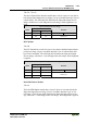
The above Incremental Encoder Interface module has 5 bytes of input data (6
bytes in cycle duration measurement mode) and 3 bytes of output data. The
following tables illustrate the Input and Output Process Image, which has 4
words mapped into each image. Word alignment is applied.
Input Process Image
Byte Destination
Offset
High Byte Low Byte
Remark
0 - S not used Status byte
1 D1 D0 Counter word
2 - (D2)*
)
not used (Periodic time)
3 D4 D3 Latch word
*
)
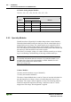
If cycle duration measurement mode is enabled in the control byte, the cycle
duration is given as a 24-bit value that is stored in D2 together with D3/D4.
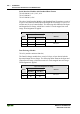
Output Process Image
Byte Destination
Offset
High Byte Low Byte
Remark
0 - C not used Control byte
1 D1 D0 Counter Setting word
2 - -
3 - -
not used
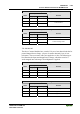
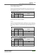
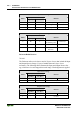
750-637
The above Incremental Encoder Interface Module has a total of 6 bytes of user
data in both the Input and Output Process Image (4 bytes of encoder data and
2 bytes of control/status). The following table illustrates the Input and Output
Process Image, which have 4 words mapped into each image. Word alignment
is applied.
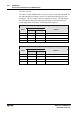
Input and Output Process Image
Byte Destination
Offset
High Byte Low Byte
Remark
0 - C0/S0 Control/Status byte of Channel 1
1 D1 D0 Data Value of Channel 1
2 - C1/S1 Control/Status byte of Channel 2
3 D3 D2 Data Value of Channel 2