
Technical data

272 • I/O Modules
Process Data Architecture for MODBUS/TCP
WAGO-I/O-SYSTEM 750
BACnet/IP Controller
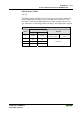
Vibration Velocity/Bearing Condition Monitoring VIB I/O
750-645
The Vibration Velocity/Bearing Condition Monitoring VIB I/O has a total of
12 bytes of user data in both the Input and Output Process Image (8 bytes of
module data and 4 bytes of control/status). The following table illustrates the
Input and Output Process Image, which have 8 words mapped into each im-
age. Word alignment is applied.
Input and Output Process Image
byte Destination
Offset
High Byte Low Byte
Remark
0 - C0/S0 Not used
Control/Status byte
(log. Channel 1, Sen-
sor input 1)
1 D1 D0
Data bytes
(log. Channel 1, Sensor input 1)
2 - C1/S1 Not used
Control/Status byte
(log. Channel 2 Sen-
sor input 2)
3 D3 D2
Data bytes
(log. Channel 2 Sensor input 2)
4 - C2/S2 Not used
Control/Status byte
(log. Channel 3 Sen-
sor input 1)
5 D5 D4
Data bytes
(log. Channel 3 Sensor input 1)
6 - C3/S3 Not used
Control/Status byte
(log. Channel 4 Sen-
sor input 2)
7 D7 D6
Data bytes
(log. Channel 4 Sensor input 2)