
Technical data

30 • Power Supply
Isolation
WAGO-I/O-SYSTEM 750
BACnet/IP Controller
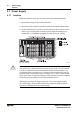
2.7 Power Supply
2.7.1 Isolation
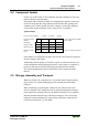
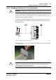
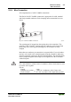
Within the field bus node, there are three electrically isolated potentials.
• Operational voltage for the field bus interface.
• Electronics of the couplers/controllers and the bus modules (internal bus).
• All bus modules have an electrical isolation between the electronics (inter-
nal bus, logic) and the field electronics. Some digital and analog input
modules have each channel electrically isolated, please see catalog.
Fig. 2-10: Isolation g0xxx01e
Attention
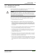
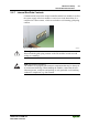
The ground wire connection must be present in each group. In order that all
protective conductor functions are maintained under all circumstances, it is
recommended that a ground wire be connected at the beginning and end of a
potential group. (ring format, please see chapter 2.8.3). Thus, if a bus module
comes loose from a composite during servicing, then the protective conductor
connection is still guaranteed for all connected field devices.
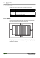
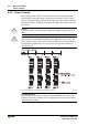
When using a joint power supply unit for the 24 V system supply and the
24 V field supply, the electrical isolation between the internal bus and the
field level is eliminated for the potential group.