
Technical data

BACnet/IP Controller 750-830 • 57
Process Image
WAGO-I/O-SYSTEM 750
BACnet/IP Controller
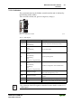
3.1.5 Process Image
Sections 3.1.5 and 3.1.6 provide a glimpse of the internal functioning, data
processing and addressing in MODBUS communication.
BACnet process data, on the other hand, are not stored in a fixed, internal
process image. Using the connected modules, the BACnet/IP controller creates
BACnet objects that represent the process data and that are not located in any
directly addressable or visible process image.
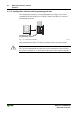
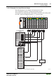
3.1.5.1 Basic Structure
After switching on, the controller identifies all bus modules connected with
the node that send or receive data (data width/bit width > 0).
A node can consist of a mixed arrangement of analog and digital modules.
Note
Using the WAGO 750-628 Internal Data Bus Extension Coupler Module and
750-627 End Module makes it possible to connect up to 250 modules to the
830-830 BACnet/IP Controller.
Attention
You can find the number of the input and output bits or bytes of the individu-
ally switched on bus modules in the corresponding descriptions of the bus
modules.
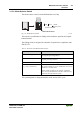
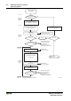
The controller creates an internal local process image on the basis of the data
width, the type of bus module and the position of the module in the node. This
is divided into an input and an output area.
The data of the digital bus modules is bit-oriented; i.e., digital data is sent bit
by bit. Analog bus modules represent all byte-oriented bus modules, which
send data byte by byte. Counter modules, DALI, MP bus, EnOcean and com-
munication modules, for example, are included in this group of bus modules.
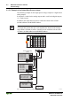
For both the local input and the output process image, the bus module data is
stored in the corresponding process image according to the order in which the
modules are connected to the controller.
First, all the byte-oriented (analog) bus modules are filed in the process image,
then the bit-oriented (digital) bus modules. The bits of the digital modules are
assembled into bytes. If the number of digital inputs and outputs is greater
than 8 bits, the controller automatically begins a new byte.