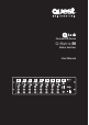
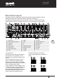
Commercial Series Q-Matrix 88 Matrix Switcher User Manual ZONE 1 ZONE 2 ZONE 3 ZONE 4 ZONE 5 ZONE 6 ZONE 7 ZONE 8 MONITOR Q-Matrix 88 MATRIX SWITCHER MIC 1 MIC 1 MIC 1 MIC MIC 11 MIC 1 MIC MIC 11 MIC 1 MIC 1 MUSIC MUSIC MUSIC MUSIC MUSIC MUSIC MUSIC MUSIC MUSIC MUSIC MASTER MASTER MASTER MASTER MASTER MASTER MASTER MASTER MASTER MASTER POWER ON OFF
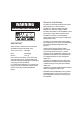
WARNING THIS APPLIANCE MUST BE EARTHED General Installation DO NOT run microphone cables near mains, data, telephone or 70V line cables. DO NOT run 100V line cable near data, telephone or other low voltage cables. DO NOT exceed 90% of the amplifiers output power when using 70V line (speech only). DO NOT exceed 70% of the amplifiers output power when using 70V line (high level background music).
Contents Introduction. . . . . . . . . . . . . . . . . . . . . . . . . . . . . . . . . . 4 Front Panel Layout. . . . . . . . . . . . . . . . . . . . . . . . . . . . . 4 Rear Panel Layout. . . . . . . . . . . . . . . . . . . . . . . . . . . . . 7 Remote Wall Panels. . . . . . . . . . . . . . . . . . . . . . . . . . . . 12 RS 485 Communication Protocol. . . . . . . . . . . . . . . . . . 13 Specifications . .
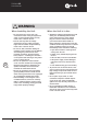
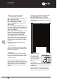
Q-Matrix 88 User Manual WARNING When Installing the Unit 2 User Manual • Do not expose the unit to rain or an environment where it may be exposed to water or other liquids as doing so may result in fire or electric shock. • Use the unit only with the voltage specified on the unit. Using a voltage higher than that which is specified may result in fire or electric shock. • Do not cut, kink, otherwise damage or modify the power supply cord.
Q-Matrix 88 User Manual CAUTION When Installing the Unit • Never plug in or remove the power supply plug with wet hands, as doing so may cause electric shock. • When unplugging the power supply cord, be sure to grasp the power supply plug; never pull on the cord itself. Operating the unit with a damaged power supply cord may cause a fire or electric shock. • When moving the unit, be sure to remove its power supply cord from the wall outlet.
Q-Matrix 88 User Manual Introduction Congratulations on your purchase of a new Q-Tech Commercial series Q Matrix 88 Matrix Switcher. As with all Quest Engineering devices, Quest Engineering products are engineered and built to a standard that will satisfy the most demanding users and environments of commercial installation audio.
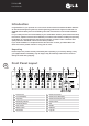
Q-Matrix 88 User Manual 1. Source Select 4. MIC1 Priority Indicator The source select button (1) is used to select the source for the zone. Each zone has a separate source selection button. There are 9 selectable sources: Line sources 1 through 8 and a local Microphone source. The MIC1 Priority Indicator LED (4) will illuminate blue indicating the Zone MIC1 priority paging function is enabled.
Q-Matrix 88 User Manual 9. Monitor ZONE SELECT 12. Monitor Volume The ZONE SELECT button (9) is used to select one of the 8 zones to be monitored. Pressing the zone select button will cycle through all zones in sequence as follows: 1, 2, 3, 4, 5, 6, 7, 8, and OFF. The Monitor Volume control knob (12) will control the in-built Monitor Speaker volume level. A zone can be selected pressing the ZONE SELECT button.
Q-Matrix 88 User Manual Rear Panel Layout Quest Engineering have designed the Q Matrix 88 to provide maximum flexibility in terms of supporting several types of inputs which may be required in an installation. The Q Matrix 88 features a bank of 8 line level inputs, a mixture of 4 phono inputs and four additional inputs which are configurable as either mic or line with phantom power available.
Q-Matrix 88 User Manual PIN 1 - [+24V DC 24V] Power supply input. (Battery Back Up or UPS) PIN 2 - [GROUND DC 24V] Power supply input. (Battery Back Up or UPS) The Matrix can be linked with a DB37 Cable. This will enable the Line 1 – 8 Sources, MIC1 Input, Paging Consoles 1 & 2, and Communication Data of the master unit to be shared with any Slave Matrix Units connected to the system.
Q-Matrix 88 User Manual Local zone source level has three adjustments, namely: a. Gain control for the local source Input on the rear of the Matrix b. A Music level control on the Matrix front panel or the remote wall control c. A Master level control on the Matrix front panel. Please Note: The input signal is set at 300mV-1.1v/10K Ohm 7. Remote Control Panel Input Each of the eight zones can have a remote control panel connected.
Q-Matrix 88 User Manual 12. HF The Zone HF Treble of the Zone Output can be controlled by adjusting the HF Treble Level Control. This Level Control will provide adjustment of the 100Hz Audio Frequency by ±10dB. Every Zone has a HF Treble Level Control which enables the HF Treble Level of each zone to be set independently of other zones. 13. Enable/Disable Switch 10 If a Zone Remote Wall Control Panel is to be used with the System, The RJ45 Remote Control Panel Input needs to be enabled.
Q-Matrix 88 User Manual The Line Inputs have an impedance of 47k ohms. 1. Line 1-8 source inputs will be selectable using the Source Select control on the front of the Matrix. 2) 2. The selected source input number will be indicated on the Matrix zone display. 3. Any extension Matrix unit connected to the system will use sources line 1-8 from the master Matrix. 4. Only one set of input sources for lines 1 -8 can will be connected per system.
Q-Matrix 88 User Manual Remote Wall Panels 86mm 86mm 146mm 146mm 12 • Up to 8 x Remote wall panels can be connected to a single Q Matrix 88 unit (with only one per zone). • There are 2 types of remote wall control panel available: QTVCS - which includes source select/Volume Control and the QTIWML - which has both MIC and Line inputs.
Q-Matrix 88 User Manual RS 485 Communication Protocol Baud Rate: 57600bps/S Parity Check: Odd parity check Data: 16 bytes Accumulation = 2nd data byte + 3rd data byte + 4th data byte Q Matrix 88 Inquiry Data The Q Matrix 88 sends inquiry data to 2 remote paging consoles, 8 remote wall panels and extension Matrix. The new data will feedback to the Matrix when any new data has been checked. Any extension Q Matrix 88 will only enquire to its own 8 remote wall panels only.
Q-Matrix 88 User Manual Feedback Data From The Wall Plate Inquiry Data To Extension Matrix The feedback data from the wall plate to the Matrix delivered in the following format: The Matrix inquiry data to the extension Matrix format as: AA 21 line input volume AM AA 30 00 00 AM AA: data head 21: feedback data from wall plate to Matrix line input: source input 01 : line 1 02 : line 2 ..........
Q-Matrix 88 User Manual Connection Diagram MIC Input 1 8 Remote Control Panels Line 1-8 Inputs ZONE 1 ZONE 2 ZONE 3 ZONE 4 ZONE 5 ZONE 6 ZONE 7 ZONE 8 1-8 Zone Speaker Outputs MONITOR Q-Matrix 88 MATRIX SWITCHER MIC 1 MIC 1 MIC 1 MIC MIC 11 MIC 1 MIC MIC 11 MIC 1 MIC 1 MUSIC MUSIC MUSIC MUSIC MUSIC MUSIC MUSIC MUSIC MUSIC MUSIC MASTER MASTER MASTER MASTER MASTER MASTER MASTER MASTER MASTER MASTER POWER ON OFF Master Matrix Link 8 Remote Control Panels Paging MIC 1
Q-Matrix 88 User Manual QTRPS Paging Console & QTEPS Extension Panels The remote paging console can work together with the Matrix to set up a 32 zone paging system. Each Matrix can accommodate 2 remote paging consoles which may be identified by dipswitch settings. Each remote paging console is designed for an eight zone paging capacity, while an extension keypad may be added where more than 8 zones (and up to 32 zones of paging) is required. A maximum of 3 extension keypads may also be added.
Q-Matrix 88 User Manual 1 Master Remote Paging Console 10 2 Extension Keypad 1 3 Extension Keypad 2 4 Extension Keypad 3 5 Gooseneck Microphone 6 Power Indicator The All Call Button can be selected when all zones are to be selected. If more than one console is being used, priority operates on this is on a “first in first served” basis. The All Call indicator will be turned off when the All Call button is pushed and the other paging consoles are in use.
Q-Matrix 88 User Manual Rear Panel POWER 24VDC CCM 15 15 2TOME OFF 4TOME 16 Power Switch The paging console is powered from the Matrix through CAT5 cable as long as the communication distance is < 50 meters 16 18 DC 24V Power Input An additional DC24V power supply is required if the distance from the paging console and Matrix is greater than 50m 17 Communication Port The communication port is an RJ45 Socket to the Matrix which uses standard Cat 5 cable User Manual Q-Tech Commercial Series Q-
Q-Matrix 88 User Manual Connection and Setting Power Supply The remote paging console is powered by the Matrix through the RJ45 communication port when the communication distance is < 50 meters. An extra DC 24V power input is equipped on the back part of the paging console to supply power when the communication distance is longer than 50 meters.
Q-Matrix 88 User Manual Wall Panels where the QT1WML is to be used. A ten step volume control is provided over all sources. A dual RCA input and a microphone XLR input are included, each with their own input level control. The communication between the panel and the Matrix is through industry standard CAT5 cable which is also used to supply power from the Matrix to this panel within 50 meters. QT1WML In-wall Mixer The QT1WML is a remote control panel designed to work together with the Q Matrix 88.
Q-Matrix 88 User Manual Connection & Wiring Power Supply 9 10 13 11 The RJ45 port is used to communicate between the remote control panel and the Matrix, it also will be used to supply power to the panel within 50 meters. A spare DC24V input is provided for extra power supply to the remote control for communication distances longer than 50 meters. The communication cable preferred is industry standard CAT5 cable. Local Source Input 12 14 The local source input through the dual RCA aux input connector.
Q-Matrix 88 User Manual Operation Power Supply The remote control panel will have active power via CAT 5 cable from the Q Matrix 88, over distances <50 meters or an external 24v supply if the distance is over 50 meters. The power indicator will turn blue, which will be as a status indicator to display the active communication between the wall panel and the Q Matrix 88.
Q-Matrix 88 User Manual QTVCS Remote Source Select/Volume Control The QTVCS is a remote control panel designed to work together with Q Matrix 88. The QTVCS is suitable for use as a remote source selector and a volume controller for signals fed into the zone via the Q Matrix 88. The remote control panel is designed with an LED to provide direct display of the selected sources, with up and down buttons to be used for changing source material from the Q Matrix 88.
Q-Matrix 88 User Manual Connection & Wiring 1 2 The RJ45 port is used to communicate between the remote control panel and the Matrix, it also will be used to supply power to the panel within 50 meters. A spare DC24V input is provided for extra power supply to the remote control for communication distances longer than 50 meters. The communication cable preferred is industry standard CAT5 cable.
www.questaudio.net Quest Engineering Pty Ltd 86 Derby St.