
User manual

QTA 1360P/1480P
User Manual
User Manual Q-Tech Commercial Series
QTA 1360P/1480P
4
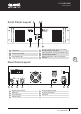
Power Source
AC Power Source
The supply transformer has been designed for
AC 240V /115V (±10%) 50 /60 Hz.
DC Power Source
Battery Connection (24Vdc)
When using external batteries, please ensure
the amplifier is grounded via the screw
terminal. (Electrical stability of the system
will be improved by providing a good earth
ground.) When connecting batteries, please
ensure correct polarity.
Main Connections
Each input has XLR and Phone jack input.
Use the one you want
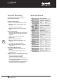
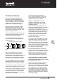
Pin Assignments:
Balanced Audio (3 pole XLR):
Pin 1: Ground / Screen
Pin 2: In phase / +ve / Hot
Pin 3: Out of phase / -ve / Cold
Unbalanced Audio (3 pole XLR):
Pin 1: Ground / Screen
Pin 2: Signal
Pin 3: Ground / Screen (connect to pin 1)
For best performance when using long lines
between microphones/mixer and or amplifier
use balanced lines. These have the effect of
canceling out any noise or hum that may be
induced into the cables.
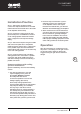
Speaker Output Connection
The speaker output screw terminal is on the
rear panel. It can connect low impedance 8
ohm, or high-level 70V or 100V speaker. Use
only one of these output connections for
corresponding speaker.
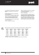
As a guide for the correct gauge of wire, we
recommend the following:
Link Output Connection
Use XRL (female) to connect booster output
to another amplifier.
A distribution amplifier should be used when
more than 6 amplifiers need to be looped.
100V
Up to 50m AWG25-26 (0.15mm2)
50m - 200m AWG20 (0.5mm2)
Over 200m AWG18 (0.75mm2)
70V
Up to 50m AWG24 (0.20mm2)
50m - 200m AWG17 (1.0mm2)
Over 200m AWG16 (1.5mm2)
Low
Impedance
(4Ω)
Up to 10m AWG18 (0.75mm2)
10m - 30m AWG13 (2.50mm2)
1
3
2
Plug
1
3
Socket
2
Viewed from Solder
Side of Plug/Soceket