
User manual

QTA 1360P/1480P
User Manual
User Manual
Q-Tech Commercial Series
QTA 1360P/1480P
7
Technical Notes
Constant Voltage Distributed
Speaker Systems Demystified
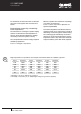
In a typical paging and background music
speaker installation, quantity loudspeakers
are placed across a single amplifier in a
parallel wiring configuration (see Fig. 1).
Each ceiling speaker will contain a small
transformer and you will notice that the
connection block near the transformer will
have a common terminal (C or earth), and a
number of wattage terminals.
Connect the wattage setting terminal for the
desired acoustic output (volume) level you
need from each individual speaker.
This will be a 100V setting in Europe and
most of Asia and 70V in the USA. (See the
explanation below)
Often some speakers need to be set at
different volume output levels, and the
calculations involved in determining the actual
load impedance at the amplifier’s output
can be quite involved but there is a simple
technique for not overloading the amplifier
As for the amplifiers, there are two common
standards, 100 Volt line in Europe and Asia
and 70 Volt line on the American continent.
For the purpose of simple calculations, we will
use the European standard for this exercise.
On the rear of a 70/100V amplifier you will find
an output terminal strip. This terminal strip
will contain a number of + voltage outputs
(70V 100V) and a terminal at one end for the
negative return wire (COM).
A low impedance terminal will be for
8-ohm speaker installations and is under
no circumstances to be connected to a
transformer type speaker system.
How to calculate the correct
number of speakers and what
wattage connection for a given
amplifier power.
If you connect too many speakers to an
amplifier you will have distortion, overheating
of the amplifier and generally poor
performance. The problem is not really “too
many speakers”, it is more a problem of “too
much wattage draw exceeding the output
capability of an amplifier. A similar problem
would be trying to draw 2,000 watts from
a 1,000 watt generator. Sooner or later….
Expect a system failure.
Let us take a 100 watt amplifier. If you have
20 speakers and you set them at the 5 watt
taping, you will have a total 100 watt draw
which is the maximum output of the amplifier.
This is correct in theory but in practice you
will be safer connecting 18 speakers, not 20.
The reason is that most ceiling speakers draw
more than their claimed wattage.
The alternative would be to connect the
speakers to the 4 watt transformer terminal
giving you a theoretical total draw of 80 watts
and thus, plenty of “headroom”. One watt
difference is not very noticeable as far as
output sound pressure level in concerned.
A system that does not distort will give
much clearer voice reproduction than a
louder system that is distorting or loosing
the sibilant frequencies.
There is a formula for testing the potential
power of the system by measuring the
impedance of each speaker and then adding
all the figures to a total impedance, which is
then compared to the amplifier’s expected
impedance/power figures. The quick way is
to just add up all the wattages and then give
yourself 10-20% headroom by reducing the
number of speakers per amplifier or lowering
the wattages slightly.
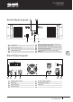
100V Line Public Address System
Remote Speaker
with 100V Line
Transformers
Fig. 1