THE NEXT GENERATION IN FLOOD PROTECTION M A N U A TM L
Table of Contents TESTED & APPROVED How They Work.................................................................................. 2 What They’re Made Of...................................................................... 2 The Flood Gate is Kitemark certified, ensuring the highest levels of quality and safety. Box Components.............................................................................. 3 Flood Gate Sizes...............................................................................
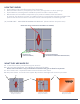
HOW THEY WORK • • • • Flood Gates quickly seal off doorways from flood water Minimize water intrusion, of depths up to 23 inches, through doors or other openings. Flood Gates are not designed to withstand impacts from debris and/or waves. Effectiveness of Flood Gates is dependent upon pressure between sides and bottom of opening. The structure in which it is installed must be in good shape and able to withstand this pressure. The structure surface must have a smooth surface capable of maintaining a seal.
Box components: BOX COMPONENTS Instructions & Operations Manual Flood Gate 17mm Ratchet Wrench Neoprene Sleeve FLOOD GATE SIZES Determine the appropriate size or mixture of sizes of Flood Gates to fit your openings. Flood Gate Size 25in- 30in Max. Expansion: 34in Height: 26.5in Flood Gate Size 40in - 45in Max. Expansion: 49in Height: 26.5in Flood Gate Size 30in- 35in Max. Expansion: 39in Height: 26.5in Flood Gate Size 45in - 50in Max. Expansion: 54in Height: 26.
PLACING THE FLOOD GATE Ideally, the Flood Gate should be placed on the outside of the property, in the reveal. All buildings differ in the amount of reveal available and their surface type; it is recommended that you check your wall and floor surfaces to ensure that water cannot seep under or around the barrier, nor into the side walls or framework. Add silicone caulk (not included) between Flood Gate and reveal as needed.
INSTALLING YOUR FLOOD GATE By following the procedures in the correct sequence, the barrier will take approximately 2 minutes to install in position. STEP ONE Ensure that your entrance is smooth and clean of dust and debris at the vertical and base area in preparation for positioning. Diagram B1 Diagram WARNING - Rough surfaces may damage the sleeve & leave area for possible seepage.
SIDE RAILS Side Rails are designed to add extra support as well as a smooth wall for a better seal. Note: If you do NOT have a standard door that fits the Flood Gate, please review the following options to adapt your door frame to accommodate the Flood Gate Many doors, particularly PVC doors, patio doors and French windows, are fitted almost flush with the outer face of the building.
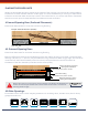
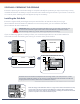
INSTRUCTIONS FOR STANCHION & SIDE RAILS To connect multiple Flood Gates together the Stanchion set must be used The parts shown in illustration (A) come in one kit with all of the necessary hardware. Illustration (B) shows the Side Rails that are sold in pairs. The condition of your existing surface and installation options should be discussed with a qualified architect, engineer or contractor. General knowledge in concrete construction is necessary for this project.
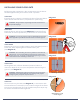
SIDE RAILS: PREPARING THE OPENING Ensure the planning and evaluation stage is complete. Identify the products you require and carry out any remedial work that is necessary to square and even wall reveals and ground area. If your frame is not secure or is uneven, then installing side rails (optional) may be necessary. Installing the Side Rails Ensure the right and left jamb edges are square with the floor at least 30 inches (76 cm) high. (See illustration E and illustration F).
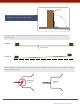
Add Filler Piece C It may be necessary to make filler pieces to make rails4 square to mounting surface. 3 D D C 4 90° 2 3 1 2 1 The faces of the structure adjacent toBwhere the rails will be mounted must be parallel and in line with each other. Correct: Straight Edge C B Incorrect: (Not Straight) A B Be sure screws are flush with the inside surface of the rail leakage. Failure to do so could result in damage 4 3 2 4 1 3 2 1 to the neoprene sleeve.
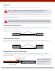
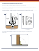
BORING THE HOLES FOR THE BASE STANCHIONS: LAYING OUT THE HOLE LOCATION ILL I CENTER LINE OF STANCHION I BORING THE HOLES 90º FOR THE BASE ILL I 3” CENTER LINE OF STANCHION STRAIGHT RIGID LINE MARKED STEEL GUIDE BAR ACROSS BAR 90º 3” SHIMS OR CLAMPS ON BOTH ENDS AS SHOWN CAUTION: Whether or not you opt to use the Side Rails, the 3 in. / 76.
ASSEMBLING THE ANGLE BRACKETS TO THE BASE When the holes are bored and cleaned you are ready to set up the Base. 1. Assemble the two angle brackets to the Base using the four allen head cap screws. Finger tighten at this point. (See illustration K) NOTE: The angle brackets are used to support the Base in position while cement cures. Once curedthey will be removed & discarded. (See illustration N). 2. Using a small square adjust the front angle bracket so it’s square to the top side edge of the Base.
INSERTING BASE ASSEMBLIES Pour and fill the hole with concrete to a depth of 4 inches from the top and tap or vibrate the concrete to ensure it completely settles at the bottom of the hole. Position the Base down into the concrete. 1. Align the center line marks on the angle brackets with the line marks on the center edge. (See illustration P). Ensure you clamp the center line marks together so that both angle brackets are resting flat on the surface of the floor. (See illustration N).
GENERAL MAINTENANCE AND INSTALLATION Removing the clamp Keep the allen screws and allen wrench in a safe place as they will be needed to secure the Stanchion to the Base in the event of a flood. Maintaining the Base 1. There are (4) 1/2 in. - grub screws with every Stanchion. These must be coated with a waterproof grease or anti-seize compound and screwed into the holes on each plate.
AFTER-USE Flood Gate Maintenance Instructions 1. Return the horizontal and vertical operating mechanisms to their closed position. 2. Remove the unit from its position. 3. Remove the sleeve and examine for damage caused by stress, use or wear and tear. Repair or replace as necessary. 4. The sleeve can be hand washed in warm water up to 104° F (40° C). Rinse in cold water and hang to dry in shaded area. DO NOT TUMBLE DRY. 5. Dry off excess moisture from the metal frame.
Be Prepared & Be Protected PROTECTING THESE INDUSTRIES Government Property Management Construction Universities Hospitals Janitorial Hotels Retail Grocery Residential & MORE Visit us at www.quickdams.com or call 888-761-4405 © 2019 Quick Dam, Flood Gate & Absorbent Specialty Products. All rights reserved. No part of this manual may be reproduced, distributed, or transmitted in any form or by any means, without consent from Quick Dam & Absorbent Specialty Products.