
Full Product Manual


11
Flood Gate Manual | www.quickdams.com
Once the brackets are assembled to the Base, measure and mark the centerline on
each angle bracket. These lines will be used to position the Base in the bored hole
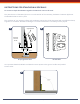
PREPARING THE GROUND SURFACE AND BASE RECESS
Concreteoorsandslabsvarygreatlyintermsofthicknessandtype
of concrete. You must create a recess beneath the surface for the
anchor which is then set in the concrete foundation. With this style
ofconstructiontheriskassociatedwithundersizeoorthickness,
cracks and inadequate concrete reinforcement is greatly reduced.
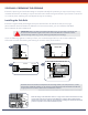
The two angles are the same, but the Front Angle
Bracket is the one which is the positioning gauge for
each Stanchion, therefore it must be squared with the side
edge of the Base prior to tightening. (See illustration K).
The Rear Angle Bracket need not be squared.
Top View: Face (A) and (B) must be
square to each other as shown. A simple
6 in. square works nicely for this.
Side View
90º
A
B
FRONT
ANGLE
BRACKET
REAR
ANGLE
BRACKET
8”
10”
EXISTING
CONCRETE
SLAB
EXISTING
CONCRETE
SLAB
SUB
SOIL
SUB
SOIL
EXISTING
CONCRETE
SLAB
POSITIONING GAUGE
ANGLE FRONT
SUPPORT RIB
FACES TOWARDS
OUTSIDE OF
BUILDING
CENTER LINE OF ANCHOR
SHOULD BE ON CENTER
LINE OF HOLE AS SHOWN
OUTSIDE OF BUILDING
ANCHOR
ASSEMBLY
ANCHOR
ASSEMBLY
TOWARDS
FLOOD
WATER
A A
B B
C C
D D
4
4
3
3
2
2
1
1
DO NOT SCALE DRAWING
square
SHEET 1 OF 1
UNLESS OTHERWISE SPECIFIED:
SCALE: 1:4
WEIGHT:
REV
DWG. NO.
C
SIZE
TITLE:
NAME
DATE
COMMENTS:
Q.A.
MFG APPR.
ENG APPR.
CHECKED
DRAWN
FINISH
MATERIAL
INTERPRET GEOMETRIC
TOLERANCING PER:
DIMENSIONS ARE IN INCHES
TOLERANCES:
FRACTIONAL
ANGULAR: MACH
BEND
TWO PLACE DECIMAL
THREE PLACE DECIMAL
APPLICATION
USED ON
NEXT ASSY
PROPRIETARY AND CONFIDENTIAL
THE INFORMATION CONTAINED IN THIS
DRAWING IS THE SOLE PROPERTY OF
<INSERT COMPANY NAME HERE>. ANY
REPRODUCTION IN PART OR AS A WHOLE
WITHOUT THE WRITTEN PERMISSION OF
<INSERT COMPANY NAME HERE> IS
PROHIBITED.
A
B
90º
A
B
FRONT
ANGLE
BRACKET
REAR
ANGLE
BRACKET
8”
10”
EXISTING
CONCRETE
SLAB
EXISTING
CONCRETE
SLAB
SUB
SOIL
SUB
SOIL
EXISTING
CONCRETE
SLAB
POSITIONING GAUGE
ANGLE FRONT
SUPPORT RIB
FACES TOWARDS
OUTSIDE OF
BUILDING
CENTER LINE OF ANCHOR
SHOULD BE ON CENTER
LINE OF HOLE AS SHOWN
OUTSIDE OF BUILDING
ANCHOR
ASSEMBLY
ANCHOR
ASSEMBLY
TOWARDS
FLOOD
WATER
K
M
N
L
TOP
BOTTOM
Flood water
comes from
this side
Ground
UNDERGROUND
Upright Stanchion
Base
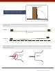
ASSEMBLING THE ANGLE BRACKETS TO THE BASE
When the holes are bored and cleaned you are ready to set up the Base.
1. Assemble the two angle brackets to the Base using the four allen head cap screws.
Finger tighten at this point. (See illustration K)
NOTE: The angle brackets are used to support the Base in position while cement cures. Once cured-
they will be removed & discarded. (See illustration N).
2. Using a small square adjust the front angle bracket so it’s square to the top side edge
of the Base. (see illustration K, L and N).
3. While holding the front angle bracket square to the Base, tighten all four cap screws.
4. Re-check the front angle bracket again with the square (see illustration L).
5. Firmly clamp or block shim each end of the rigid straight edge into the Side Rails and against
the oor. Ensure that the centerline marks (which are put on to the straight edge earlier - see
illustration I) are facing upward as these are the marks which you must later line up with the centerline
marks scribed on to the face of the angle brackets (see illustration M).