
Full Product Manual


12
Flood Gate Manual | www.quickdams.com
INSERTING BASE ASSEMBLIES
Pour and ll the hole with concrete to a depth of 4 inches from the top and tap or vibrate the concrete to
ensure it completely settles at the bottom of the hole. Position the Base down into the concrete.
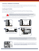
1. Align the center line marks on the angle brackets with the line marks on the center edge. (See illustration P).
Ensureyouclampthecenterlinemarkstogethersothatbothanglebracketsarerestingatonthesurfaceoftheoor.
(See illustration N).
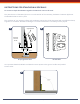
NOTE: Each Base is designed with a 3” x 3” hollow square tube. At the very top of the tube and
through its rear wall, just under the threaded plate, there is a 3/4” hole in the tube. This hole allows air to
escape from the inside of the tube while the inside is lling with concrete. (See illustration O)
2. While lling with concrete, gently tap on the very
center of the top of the Base with a block of wood
or handle end of a hammer.
ItiscriticalthattheinsideoftheBaseiscompletelylledwith
concrete to maintain maximum strength.
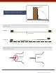
3. Ensure the top edge of angle brackets are ush with the
surface of the ground.
Do not remove the clamps and angle brackets for at least 24 to 36
hours depending on the temperature, humidity and soil mechanics to
allow concrete to set.
AIR
RELIEF
HOLE
RIDGED
STRAIGHT
EDGE
CLAMP (4)
(not included)
Center line mark on
face of Angle Bracket
must line up with
marks on Ridged
Straight Edge
Center line mark on
Face of front angle
Bracket
Dimension B
from ILL J
Straight Edge
C-Clamps
Align center mark with
line on the straight edge
A A
B B
C C
D D
4
4
3
3
2
2
1
1
DO NOT SCALE DRAWING
boring the holes
SHEET 1 OF 1
UNLESS OTHERWISE SPECIFIED:
SCALE: 1:24
WEIGHT:
REV
DWG. NO.
C
SIZE
TITLE:
NAME
DATE
COMMENTS:
Q.A.
MFG APPR.
ENG APPR.
CHECKED
DRAWN
FINISH
MATERIAL
INTERPRET GEOMETRIC
TOLERANCING PER:
DIMENSIONS ARE IN INCHES
TOLERANCES:
FRACTIONAL
ANGULAR: MACH
BEND
TWO PLACE DECIMAL
THREE PLACE DECIMAL
APPLICATION
USED ON
NEXT ASSY
PROPRIETARY AND CONFIDENTIAL
THE INFORMATION CONTAINED IN THIS
DRAWING IS THE SOLE PROPERTY OF
<INSERT COMPANY NAME HERE>. ANY
REPRODUCTION IN PART OR AS A WHOLE
WITHOUT THE WRITTEN PERMISSION OF
<INSERT COMPANY NAME HERE> IS
PROHIBITED.
P
O
Straight Edge
C-Clamps
Align center mark with
line on the straight edge
A A
B B
C C
D D
4
4
3
3
2
2
1
1
DO NOT SCALE DRAWING
boring the holes
SHEET 1 OF 1
UNLESS OTHERWISE SPECIFIED:
SCALE: 1:24
WEIGHT:
REV
DWG. NO.
C
SIZE
TITLE:
NAME
DATE
COMMENTS:
Q.A.
MFG APPR.
ENG APPR.
CHECKED
DRAWN
FINISH
MATERIAL
INTERPRET GEOMETRIC
TOLERANCING PER:
DIMENSIONS ARE IN INCHES
TOLERANCES:
FRACTIONAL
ANGULAR: MACH
BEND
TWO PLACE DECIMAL
THREE PLACE DECIMAL
APPLICATION
USED ON
NEXT ASSY
PROPRIETARY AND CONFIDENTIAL
THE INFORMATION CONTAINED IN THIS
DRAWING IS THE SOLE PROPERTY OF
<INSERT COMPANY NAME HERE>. ANY
REPRODUCTION IN PART OR AS A WHOLE
WITHOUT THE WRITTEN PERMISSION OF
<INSERT COMPANY NAME HERE> IS
PROHIBITED.