Instructions & Operator Manual
TABLE OF CONTENTS Product Information........................................................................Pg. 1 Gate Sizes...............................................................................Pg. 2 Doorway Anatomy...........................................................................Pg. 2 Where to Place the Gate................................................................ Pg. 3 Fitting Instructions........................................................................... Pg.
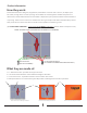
Product Information How they work: Flood Gates have been designed, engineered, and tested to minimize water intrusion, of depths up to 23 inches, through doors or other openings. Flood Gates are not designed to withstand impacts from debris and/or waves. Effectiveness of Flood Gates is dependent upon pressure between sides and bottom of opening. The structure in which it is installed must be in good shape and able to withstand this pressure.
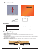
Box components: Flood Gate Neoprene Sleeve 17mm Ratchet Wrench Instructions & Operations Manual Gate sizes QDFG30 Fits openings 30” – 35” QDFG35 Fits openings 35” – 40” QDFD40 Fits openings 40” – 45” QDFG45 Fits openings 45” – 50” Note: For openings wider than 50”, stanchions must be used. See Flood Gate Stanchion Installation & Maintenance section of this manual on page 8. Doorway anatomy: 1. Width of opening (wall to wall within the reveal) 2.
Where to place the gate: Ideally, the Flood Gate should be placed on the outside of the property, in the reveal. All buildings differ in the amount of reveal available and their surface type; it is recommended that you check your wall and floor surfaces to ensure that water cannot seep under or around the barrier, nor into the plasterwork. Add silicone caulk between Flood Gate and reveal as needed. Example: Preferred Placement.
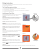
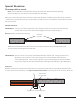
Fitting Instructions The Flood Gate is designed to seal off doorways from flood water. It can be reused for many years, but must be properly maintained. The Flood Gate system includes: 1. 2. 3. 4. A metal frame expanding both horizontally and vertically - see Diagram A. A neoprene sleeve - see Diagram B. The rear of the sleeve allows access to the scissor jack and lower bolts - see Diagram C.
After-use Maintenance Instructions 1. Return the horizontal and vertical operating mechanisms to their closed position. 2. Remove the unit from its position. 3. Remove the sleeve and examine for damage caused by stress, use or wear and tear. Repair or replace as necessary. 4. The sleeve can be hand washed in warm water up to 104° F (40° C). Rinse in cold water and hang to dry in shaded area. DO NOT TUMBLE DRY. 5. Dry off excess moisture from the metal frame.
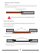
Special Situations: Doorways with no reveal: Note: If you do NOT have a standard door that fits the Flood Gate, please review the following options to adapt your door frame to accommodate the Flood Gate. Many doors, particularly PVC doors, patio doors and French windows, are fitted almost flush with the outer face of the building. In these situations, you would need to consider how you can extend the reveal sufficient to allow the barrier to work.
Openings too wide for Flood Gates: Example 3. If opening is greater than 50”, additional frame may be added to decrease opening size. However, please ensure that the screw heads do not protrude from the frame or stanchion and side rails (optional) may be used to connect multiple units together. Apply silicone caulk on outside joints and along bottom of the new frame.
To connect multiple Flood Gates together the stanchion set must be used Instructions for Stanchion & Side Rails (both optional) The parts shown in illustrations (A) and (B) come in one kit with all of the necessary hardware. Illustration (C) are the Side Rails & are sold in pairs.
PREPARING THE OPENING Ensure the planning and evaluation stage is complete and you have identified the products you require and carried out any remedial work that is necessary to square and even wall reveals and ground area. If your frame is not secure or is uneven, then installing side rails (optional) may be necessary. Installing the Side Rails Ensure the right and left jam plates are square with the floor at least 30 inches (76 cm) high. (See illustration E and illustration F).
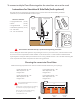
BORING THE HOLES FOR THE BASE ILL I CENTER LINE OF STANCHION 90º 3” STRAIGHT RIDGED GUIDE BAR SHIMS OR CLAMPS ON BOTH ENDS AS SHOWN Whether or not you opt to use the side rails, the 3 in. / 76.2 mm centerline dimension of the bored stanchion holes must always be maintained from whatever surface the back CAUTION: face of the Flood Gate comes into contact with on the opening. An engineer will advise on the most appropriate method of boring the hole.
ASSEMBLING THE ANGLE BRACKETS TO BASE When the holes are bored and cleaned you are ready to set up the base. 1. Assemble the two angle brackets to the base using the four allen head cap screws. Finger tighten at this point. (See illustration K) NOTE: The front of the base is where the support rib is located (See illustration N). 2. Using a small square adjust the front angle bracket so it’s square to the top side edge of the base. (see illustration K, L and N). 3.
INSERTING BASE ASSEMBLIES Pour and fill the hole with concrete to a depth of 4 inches from the top and tap or vibrate the concrete to ensure it completely settles at the bottom of the hole. Position the base down into the concrete. 1. Align the center line marks on the angle brackets with the line marks on the center edge. (See illustration P). Ensure you clamp the center line marks together so that both angle brackets are resting flat on the surface of the floor. (See illustration N).
GENERAL MAINTENANCE AND INSTALLATION Removing the clamp Keep the Allen Screws and Allen Wrench in a safe place as they will be needed to secure the stanchion to the Base in the event of a flood. ILL Q Maintaining the Base 1. There are (4) 1/2 in. - grub screws with every stanchion. These must be coated with a waterproof grease or anti-seize compound and screwed into the holes on each plate.
Terms & Conditions Flood Gate is intended to be used as outlined in this document and other Absorbent Specialty Products (ASP) literature. Data and information provided in this document is for general information purposes only. Conditions for each use of the Flood Gate will vary and are beyond the control of ASP. ASP cannot guarantee desired results.