
Specifications


DATA SHEET QF4A512
Rev D4, Dec 07 24 www.quickfiltertech.com
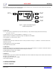
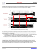
which clocks are derived to drive the FIR filters, the ADC and the analog front end. The master clock is also divided down to provide a
clock to be used for transfers to the on-chip EEPROM.
Figure 7. System Clocks Block Diagram
(Default settings shown)
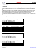
9.1 PLL Clock
The PLL clock frequency is determined by the input clock frequency, f
0
, the pre-divider value (M) and the divider value (N):
PLL_CLK = f
0
* N / M
The default frequency for PLL_CLOCK is 200MHz. (f
0
= 20MHz, M = 1, N= 10)
Operation of the PLL is possible in two frequency ranges: 20-100MHz and 100-300MHz.
Control registers: PLL_CTRL0 and PLL_CTRL1
9.2 System Clock
The System Clock (SYS CLK) is divided down from PLL CLK by a number in the range 1 – 64, default = 1. SYS CLK is used as the
reference for the FIRs.
The default frequency for SYS CLK is 200MHz.
Control register: SYS_CLK_CTRL
9.3 ADC Clock
The ADC Clock (ADC CLK) is also divided down from PLL CLK. The range of divisor values is 2 -16, default = 2. ADC CLK is used to
drive the ADC (including CIC and CIH blocks) and other analog front end blocks.
The default frequency for ADC_CLK is 100MHz.
Control register: ADC_CLK_RATE
9.4 EE Clock
The EE Clock (EE CLK) is used for transfers to/from EEPROM. This clock is divided down directly from the master clock with divisors in
the range 1 – 32, default value = 16.
The default frequency for EE_CLK is 1.25MHz.
Control register: STARTUP
10. SERIAL INTERFACE
10.1 Modes of Operation
XTAL or
EXT CLK
OSC /1
VCO
Φ
/10
/1
/2
/16
PLL
EE_CLK
1.25MHz
ADC_CLK
100MHz
SYS_CLK
200MHz
PLL_CTRL0
(1 – 64)
PLL_CTRL1
(1 – 64)
SYS_CLK_CTRL
(1 – 64)
ADC_CLK_RATE
(2 – 16)
STARTUP_1
(1 – 32)
PLL_CLK
f
0
, 20MHz
200MHz