
Specifications


DATA SHEET QF4A512
Rev D4, Dec 07 38 www.quickfiltertech.com
pcg_chN_en
*0 = Disabled
1 = Enabled
Description: Enables the ADC clock and system clock for channel N.
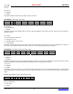
0Ah ENABLE_1 (AAF Enable, ADC Mode)
Bit 7 Bit 6 Bit 5 Bit 4 Bit 3 Bit 2 Bit 1 Bit 0
Address 0Ah X X afe_opmadc1 afe_opmadc0 afe_opmfec4 afe_opmfec3 afe_opmfec2 afe_opmfec1
afe_opmfecN
* 0 = Powered Down
1 = Enabled
Description: Enables the anti-aliasing filter for channel N. Must be enabled for the channel to be used, this bit is for power savings on
disabled channels.
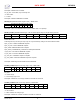
afe_opmadc
* 00 = Powered Down (10uW, 5us)
01 = Sleep (2mW, 0.5us)
10 = Standby (22mW, 12 clock cycles)
11 = Active (80mW)
Description: Sets the operating mode of the ADC. These bits can be used to conserve power in duty cycle applications. The mode can
be chosen to trade off power savings versus time to return to an active state (approximate values as shown).
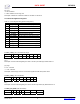
0Bh ENABLE_2 (Sampling Enable, Serial output enable)
Bit 7 Bit 6 Bit 5 Bit 4 Bit 3 Bit 2 Bit 1 Bit 0
Address 0Bh sif_ch_en4 sif_ch_en3 sif_ch_en2 sif_ch_en1 arec_ch_en4 arec_ch_en3 arec_ch_en2 arec_ch_en1
arec_ch_enN
0 = Disabled
*1 = Enabled
Description: Controls the input mux and enables sampling for channel N. This bit should be disabled only for power savings on unused
channels. Disabling a channel will alter the effective sampling rate for the remaining active channels.
Sif_ch_enN
*0 = Disabled
1 = Enabled
Description: Controls the output mux. In multi-channel mode enables channel N in the serial output data stream. In single-channel
mode identifies which channel is enabled in the serial output data stream. If two or more bits are set the lowest channel set will be
output.
0Ch PLL_SIF_STAT (PLL status, serial interface status)
Bit 7 Bit 6 Bit 5 Bit 4 Bit 3 Bit 2 Bit 1 Bit 0
Address 0Ch X X X X X X ism_pll_lock pll_lock
pll_lock – READ ONLY
* 0 = Not locked.
1 = Locked.