Powered Wheelchair Instructions for Use Hula 21417002
User Information Intended use power wheel wheelchairs: This power wheelchair was designed for persons whose ability to walk is impaired but who have sufficient eyesight and have the physical and mental attributes to be able to operate an electric wheelchair safely. It has been classified according to EN 12184 as a class A mobility product (indoor use).
1.0 Your Wheelchair 5 2.0 How to use this manual 5 2.1 Introduction 2.2 Guarantee 2.3 Warranty conditions 5 5 5 3.0 Label Explanation / Word definitions 6 4.0 General safety warning and user tips 8 3.1 Definitions of words used in this manual 3.2 Label explanations 6 7 4.1 General warnings 4.2 Features and options 4.3 Obstacles 4.4 Routine service 4.5 Brake release 4.6 EMC - Radio transmitting devices. 4.7 Emergency braking 4.8 Sharp turns 4.
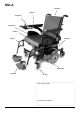
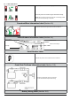
HULA Backrest Armrest Controller Side Guard Cushion Legrest Batteries Drive wheel Footplate Castor Service Agent Details: Wheelchair Serial Number: 4 HULA Rev.1.
1.0 Your Wheelchair 2.0 How to use this manual We at Sunrise Medical want you to get the best out of your Hula wheelchair. This Owner’s Manual will familiarise you with the wheelchair and its features. It contains hints on everyday usage and general care in addition to information on the high quality standards which we adhere to and details about the guarantee. 2.
4) Any repaired or replaced part will benefit from these arrangements for the balance of the warranty period applicable to the wheelchair. 3.0 Label Explanation / Word definitions 3.1 Definitions of words used in this manual 5) Parts replaced after the original warranty has expired are covered for a further twelve months.
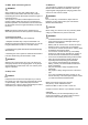
3.2 Label explanations Drive lever position for normal driving by the user. Drive lever position for manoeuvring the wheelchair manually. NOTE: The drive levers must be returned to the normal driving position as soon as manual positioning is completed Freewheel/Drive Information Label (Section 4.0) The wheelchair is intended for indoor use. Outdoor use must be in accordance with the advice given within this Owner’s Manual. Indoor/Outdoor Information Label (Section 4.
4.0 General safety warning and user tips 4.1 General warnings 4.4 Routine service The recommended service interval is one year. See service history table, section 14. WARNING! • • • • • • • Always ensure that your wheelchair is switched off before attempting to transfer in or out. Always ensure that you are able to operate all controls from a comfortable position. Paying attention to your posture is essential to ensure your continued comfort and well being.
4.6 EMC - Radio transmitting devices. WARNING! When operating two-way radio, walkie-talkies, C.B., amateur radio, public mobile radio and other powerful transmitting devices the wheelchair should be brought to a halt and turned off. The operation of cordless, mobile telephones and cell phones including hands-free devices is permitted but if abnormal operation of the wheelchair is encountered then the wheelchair must be brought immediately to a halt and turned off.
4.11 Weight limit DANGER! The user plus items carried should never exceed a total weight of 136Kg. Never use this wheelchair for weight training if the total weight (user plus additional weights) exceed a total weight of 136Kg. Exceeding the weight limit is likely to damage the seat, frame or fasteners and may cause severe injury to you or others from wheelchair failure Exceeding the weight limit will void the warranty. 4.
4.16 Adverse conditions Please be aware that when driving your wheelchair in adverse conditions, e.g. on wet grass, mud, ice, snow or other slippery surfaces, you may experience a reduction in the grip and traction of your wheelchair. WARNING! • • • We recommend you take extra precautions in these conditions, particularly on hills and slopes; your wheelchair could become unstable or skid causing possible injury. Take extra precautions when using your wheelchair during darkness or in poorly lit areas.
4.19 Use on a slope Your wheelchair has been designed and tested to allow its use on slopes or gradients of up to 6°. However, you have the option of adjusting your seating position. Please see warnings below. WARNING! In certain circumstances your wheelchair could become unstable. Before attempting to climb or descend a slope or a kerb, caution should be taken when using weight shift options and/or using your body positioning for a counter balance weight.
4.21 Stability of your wheelchair Please follow the user instructions in this manual regarding the use of your wheelchair on a slope. WARNING! Other variables can affect your wheelchair stability, including: • Movement of the user. • Effects of the addition of accessories or other equipment. • Inappropriate adjustments or modifications to the wheelchair.
4.23.1 Mounting a low kerb or step WARNING! • WARNINGS! Approach the kerb at a 90° angle and stop the wheelchair as soon as the castor wheels touch the kerb. Apply sufficient power to the motors to lift the front of the wheelchair up onto the kerb (or step) and then apply slightly more power and speed so that the drive wheels climb the kerb (or step) smoothly and without hesitation and the rear castor wheels come up as well. As far as possible, keep the joystick in the straight forward position, (Fig.4.
4.24 Anterior Pelvic Support Fig. 4.8 The Anterior Pelvic Support kit. (Fig. 4.7). Fastening the anterior pelvic support: Insert the 3 prong male buckle into the female buckle until a click is heard (Fig. 4.8) To fit the anterior pelvic support. • Place the strap loosely across the seat with the buckle closed.. (Fig. 4.9) • Pass the other ends of the strap through the gap between the backrest posts and the backrest upholstery as shown. (Fig. 4.
4.25 VR2 Controller (Fig. 4.14) Battery Level Indicator Horn 5.0 On/Off Button 5.1 Preparing your wheelchair for use Handling the wheelchair Speed Indicator NOTE: To dismantle the wheelchair for storage no tools are required. The following parts can be removed: Speed Buttons 1 pair of swing-away legrests. 1 backrest. 1 drive unit with seat frame Joystick 5.2 • • • • Preparation for every day storage Remove the swing-away legrests, (Fig.5.0). Leave the armrests in the fold down position. (Fig.5.
DANGER! WARNINGS! • • • Make sure that when the wheelchair is stored the controller is switched off and the freewheel mechanisms are engaged, (in Drive). Do not lift the wheelchair by any of the plastic shrouds. Caution should be taken while the wheelchair is in freewheel. To remove the control pod/joystick: • Loosen the adjustment screw on the control arm and slide the arm out of the bracket, (Fig 5.4). • Disconnect the control loom plug located under the seat, (Fig.5.
5.5 Control pod joystick unit position Fig. 5.10 WARNING! • Make sure that the control pod/joystick is mounted securely and that the joystick position is correct. The hand or limb you use to operate the joystick should be supported, for example by the arm pad. Do not use the joystick as the sole support for your hand or limb - wheelchair movements and bumps could upset your control of the joystick.
5.7 Armrests 5.7.1 Armrests-flip up The armrests on both sides of the wheelchair can be flipped up to allow side transfer, (Fig. 5.11-5.12). For side transfer flip the armrest all the way up until it goes into its mechanical stop. This frees your space for side transfer. To bring the armrests back into their position flip it all the way down until it sits on its mechanical stop. Guide it in its downward movement and do not let it fall on its own. Fig. 5.11 Fig. 5.12 5.7.
2.Basic coarse adjustment. PART 1 1. To achieve more than one inch of adjustment, remove the 6mm armrest rotation bolts on both sides of the seat, (Fig.5.17). 2. Remove both armrest assemblies. (Fig.5.18) 3. Remove both sets of 4mm armrest adjustment ring bolts.(Fig.5.19) 4. Rotate the armrest height adjustment rings, (Fig.5.20) to match the desired height designated in the Configuration Chart, (Fig.5.29), on page 23. 5.
PART 2 Loosen the 4mm arm pad angle pivot bolts (A) on both armrests. Remove the 4mm angle index bolts (B) on both armrests, (Fig.5.24). Use the 5mm fine height adjustment screw (B) to finish fine tuning the height. Turn counter-clockwise to increase height or clockwise to lower, (Fig.5.25). Tilt both arm pads down, (or up in the case of a lowered armrest), until the arm pads are in the preferred angle. Check to see if the height is correct, (Fig.5.26). Refer to 2 for fine adjustment.
Table Showing Backrest Angle - Arm Rest Height and Corresponding Setting Ring Position A POSITION A B POSITION B C POSITION C STANDARD CONFIGURATION CHART BACKREST ANGLE (Degrees) ARMREST HEIGHT (mm) SETTING RING POSITION -4 305 - 254 A -4 252 - 229 B 0 305 - 254 A 0 252 - 229 B 4 305 - 267 A 4 279 - 229 B 8 305 - 229 B 12 305 - 229 B 12 248 - 229 C Fig. 5.29 22 HULA Rev.1.
5.7.3 Arm pad Position Adjustment (Fig.5.30-5.33) Fine arm pad position adjustments (2.5cm-5.0cm, 1”-2”) are possible by loosening the 4mm arm pad adjustment bolts (E) and sliding the arm pad forward or backward as required, (Fig.5.30, 5.31). Access to the rear adjustment bolt may require pivoting the arm pad Retighten both adjustment bolts (E). Use 10 Nm or 88.5lbf/in of torque, (Fig.5.32). NOTE: If more than one to two inches of adjustment is required, refer to chart below, (Fig.5.33). Fig. 5.
5.8 Leg Rests Fig. 5.33 Fig. 5.34 Fig. 5.35 Fig. 5.36 Fig. 5.37 Fig. 5.38 WARNING! • • • • Be aware of your environment to make sure you do not injure your legs when Leg Rests are extended. Always ensure that the Leg Rests or foot plates do not come into contact with the castors before driving the wheelchair. Leg Rests are not to be used for lifting or carrying the wheelchair under any circumstances. As with all moving parts be careful not to trap your fingers. 5.8.
5.8.2 Foot plates The foot plates may be flipped up to aid entry and exit from the wheelchair. WARNING! Do not use the foot plates to stand on as the full weight of your body may cause the wheelchair to tip forwards. This could result in injury and could damage the foot rests. 5.8.3 Adjusting the foot rest length To adjust the foot rest length: • Loosen the bolt on the foot rest stem, (Fig. 5.39). • Adjust the length to suit, (Fig.5.40). • Ensure the bolt is firmly located and tightened prior to use. 5.8.
6.0 Seating 6.1 Firm seat board The firm seat board is designed to allow pressure relief cushions such as Jay to be used, (Fig.6.1). 6.2 Seat cushions Seat cushions supplied by Sunrise Medical will have Velcro® strips that correspond to patches on the seat, (Fig.6.2). 6.6 Seat width adjustment 1. Remove the 5mm width adjustment bolts (A) and the 4mm towel bar adjustment bolt (B), (Fig.6.5) . 2. Move the left side seat rail, armrest and backrest assembly to the desired position.
6.7 Seat height adjustment/removal Fig. 6.7 CAUTION! Specialist tools are required for this task. WARNING! • • • • • Sunrise Medical strongly recommends that the seat height adjustment is carried out by qualified/ experienced personnel. If you are unsure about carrying out this task, please ask your authorised Sunrise Medical dealer to do it for you. Ensure that the seat frame does not trap your fingers or any other part of your body.
6.8 Standard Seat Depth Adjustment 6.9 1. Remove the 5mm depth adjustment bolts from both sides of the seat, (Fig.6.11). 2. Slide the rear backrest and armrests into the desired seat depth position. Reference seat depth position patterns (A), (Fig.6.12). 3. Replace both sets of depth adjustment bolts. 4. Use 20 Nm or 177lbf/in of torque, (Fig.6.13). NOTE: Depending on the seat depth, the side guard position may have to be moved, (see section 5.8.1Fig.5.37). Backrest Angle Adjustment -4° to +12° 1.
6.10 Fig. 6.15 1. Back Height Adjustment Begin by removing the upholstery cover, (Fig.6.17). Fig. 6.17 2. Loosen the upholstery straps. It is not necessary to remove the upholstery, (Fig.6.18). Fig. 6.18 3. Reinsert and tighten both backrest bracket index bolts and bracket bolts (A & B). Use 20 Nm or 177lbf/in of torque, (Fig.6.16). NOTE: The figures below represent the 8°angle. 3. Remove the top upholstery screws.
4. Remove the 4mm towel bar bolts and the towel bar, (Fig.6.20). NOTE: This step is not necessary in every case. If the push handles are high enough, the towel bar bolts might not thread into the push handle tubes. To test, skip this step and move to Numbers 5 and 6. If the towel bar does not impede movement of the push handles, the towel bar may be left intact. 7. Replace the backpost adjustment screws. Use 10 Nm or 88.5lbf/in of torque, (Fig.6.23). Fig. 6.23 Fig. 6.20 8.
Fig. 6.26 Fig. 6.28 X Fig. 6.27 1 2 3 Fig. 6.29 0° 6.11 Mechanical Seat Tilt To set the seat tilt angle, (Fig.6.29): • • • 0º is given by bolting lower hole on seat bracket directly to the interface 3º is given by fitting tilt bracket between interface and upper hole on seat bracket 6º is given by fitting tilt bracket between interface and lower hole on seat bracket. 6.12 Centre Of Gravity (COG). 3° The seat can be moved forwards and backwards to accommodate different seat depths, (Fig.6.28).
6.13 JAY backrests The standard backrest assembly will allow the fitting of a JAY backrest, which is available as an optional extra. 7.0 Control System 6.14 Headrest To fit the Standard headrest, fit the location bracket to the push handles, using the screws and nuts supplied, ensuring that they are fully tightened. The on/off button applies power to the control system electronics, which in turn supply power to the wheelchairs motors. Adjusting the Headrest.
Operating the control joystick: When engaging the main On/Off button, allow a few seconds prior to moving the joystick. This allows the system to self check. If you move the joystick too soon, the battery level indicator display will not illuminate until the joystick is released. If it is off centre for more than 5 seconds a system error will occur. Whilst this is not harmful to your wheelchair, you will need to switch off and then back on to clear the system.
Charging and programming socket: WARNING! This socket should only be used for programming and charging the wheelchair. WARNING! This socket should not be used as a power supply for any other device. Connection of other electrical devices may damage the control system or affect the EMC performance of the wheelchair See section 11 about charging.
Fig.7.1 JOYSTICK CONTROL PANEL CHARGER & PROGRAMMING SOCKET BATTERY GAUGE ACTUATOR LED’s ON-OFF BUTTON ACTUATOR LED’s MAX. SPEED/ PROFILE INDICATION HORN BUTTON SPEED/ PROFILE INCREASE BUTTON SPEED/PROFILE DECREASE BUTTON VR2 CONTROL PANEL LAYOUT JOYSTICK ACTUATOR BUTTONS (Optional) VR2-L CONTROL PANEL LAYOUT SPEED INDICATOR MAX. SPEED BUTTON CONTROL PANEL ACTUATOR BUTTON CONTROL BUTTON VR2 DUAL CONTROL UNIT (Optional) Rev.1.
8.0 Troubleshooting using the VR2 Hand Control WARNING! Always consult your Sunrise Medical authorised dealer when a fault has appeared on your joystick. The battery gauge and maximum speed/profile indicator show the status of the control system. Battery Gauge is steady: This indicates that everything is OK. Battery Gauge flashes slowly: The control system is functioning correctly but the batteries need charging as soon as possible. Battery Gauge steps up: The wheelchair batteries are being charged.
Self Help Guide, (Fig.8.1). Fault code Possible cause Fig.8.1 The batteries need charging, or there is a bad connection to the battery. Check the connections to the battery. If the connections are good, try charging the batteries The left hand motor has a bad connection. Check the connections to the left hand motor. The left hand motor has a short circuit to a battery connection. Contact your Sunrise Medical Authorised Dealer The right hand motor has a bad connection.
9.0 Controller Mounts 9.3 9.1 General warnings: WARNINGS! WARNINGS! • • Do not replace the joystick knob with any unauthorised item. It may cause hazardous operation and loss of control of the wheelchair. It is important that the joystick boot is replaced if it is torn or brittle; failure to do so could cause substance damage to the controller and unexpected movement of the wheelchair.
10.0 Batteries and charging Fig.10.2 WARNING! • • • • • • • • Please read the owner’s manual supplied with the battery charger carefully. Do not expose any part of the battery to direct heat (i.e. naked flame, gas fire). When charging always place your charger on a hard surface in a room with good ventilation. You should not charge your batteries in outdoor conditions. Do not wear conductive jewellery when handling batteries. Never smoke or use naked flames when handling batteries.
10.2 Safety cut-outs (Fuses) In the event of a short circuit there are several safety systems built into your wheelchair to safeguard your electrical circuits. • • Fusible 80A links are connected into the fuse holders on the battery harnesses to protect the batteries and wiring. On some models a reset button is fitted on the front shroud. * *NOTE: This feature is not fitted on all models. To replace any fuses please contact your Sunrise Medical authorised dealer, who will also diagnose the fault. 10.
10.7 General charger information The external charger has been designed to charge two 12V Gel/AGM type batteries connected in series (= 24 V). The charger supplied uses a 3 pin Neutrik connector. No other connector type is suitable. Fig.10.7 Please read the owner’s manual supplied with the battery charger carefully. 10.
10.11 The range of your vehicle Most manufacturers of mobility products state the range of their vehicles either in the sales literature or within the Owner’s Manual. The range stated sometimes differs from manufacturer to manufacturer even though the battery size is the same. Sunrise Medical measure the range of their vehicles in a consistent and uniform manner, but variances still occur due to motor efficiencies and overall product load weight. The range figures are calculated to I.S.O. Standard 7176.
11.0 Transportation WARNINGS! A wheelchair secured in a vehicle will not provide the equivalent level of safety and security of a vehicle seating system. Sunrise Medical recommends that the user transfers to the vehicle seating and uses the vehicleinstalled restraint system wherever possible.
11.2 Occupant restraint instructions WARNINGS! • The pelvic restraint belt must be worn low across the front of the pelvis (Fig 11.2) so that the angle of the pelvic belt is within the preferred zone of 30° to 75° to the horizontal, (Fig 11.3). A steeper (greater) angle within the preferred zone is desirable i.e. closer to, but never exceeding 75°. Restraint belts must not be held away from the body by wheelchair components or parts such as the armrests or wheels, (Fig 11.4).
11.4 Crash testing on the Hula. A representative Hula wheelchair has been tested in accordance with the dynamic performance requirements specified in ISO 7176-19:2001 “Wheeled Mobility Devices for use in Motor Vehicles” using an Unwins 4 point strap restraint system, (two at the front and two at the rear), that conforms to ISO 10542 or SAE J2249 and was used in accordance with the WTORS manufacturer’s instructions. The Unwin restraint system was used for these tests.
11.6 Securing the wheelchair into the vehicle (Fig. 11.7-11.10) WARNING! All Hula wheelchairs require a four-point tie down system for transportation as shown in the photographs. On the left rear side: Use one of the rear tie down restraints, attach it as close as possible on the left rear mounting bracket to an angle of 45°, and tighten securely in accordance with the restraint manufacturers’ instructions.
Fig.12.1 Fig.12.6 Fig.12.2 Fig.12.7 Fig.12.3 12.3 Fig.12.4 Castor wheel replacement To remove the Castor Wheel • Ensure that the wheelchair brake release levers are in the DRIVE position. • With all wheels still on the ground, use a 17.0mm spanner and a 14.0mm socket wrench to partially loosen the axle nuts, (Fig.12.8). • Lift the wheel off the ground & secure the wheelchair with blocks or stands, (Fig.12.9). • Withdraw the loosened axle stud, (Fig12.10).
Fig.12.9 12.5 Inspection of the upholstery/seating Tears, dents, wearing or slackening of upholstery particularly near to metal could result in poor posture or lower levels of comfort and pressure relief. 12.6 Cleaning seating • You can wash all parts of the covers with a gentlewash detergent at 40°C. • You can spin-dry the covers. CAUTION! Do not dry the covers in a dryer. Fig.12.10 • • • • You can remove all parts of the covers independently of each other and wash them separately.
12.7 Cleaning controls Clean the control system and the joystick with a cloth dampened with diluted detergent. Fig.12.12 WARNING! • • • Ensure that the control system is turned off and the control pod/joystick loom plug is disconnected, (Section 5.2). Be careful when cleaning the joystick. Never use abrasive or spirit based cleaners 12.
12.10 Shipping & Storage Requirements: Storage temperature & humidity: Storage Temperature: Min: -40ºC Max: 65ºC Relative Humidity ( non-condensing): Min:5% Max: 95% Special shipping requirements: The wheelchair may be transported by road, rail, sea or air and the batteries conform to IATA regulations. 12.11 Authorised Sunrise Medical service agents The annual full service must be performed by an approved Sunrise Medical authorised dealer.
12.12 R ecommended maintenance routines (Fig.12.18) Tools required: Battery charger, Stiff brush, Petroleum jelly, Cleaning cloth and dilute disinfectant. CAUTION! Please refer to the table below, (Fig.12.17), for any information about Torques. Fastener Matrix WARNING! If in any doubt about performing any maintenance on your wheelchair, contact your Sunrise Medical authorised dealer.
12.13 Performance checks After performing any maintenance or repairs on the wheelchair you must make sure that it is functioning correctly before it is used. • Visually inspect the wheelchair to make sure the legrests, armrests etc are correctly positioned and attached to the wheelchair and all fasteners are sufficiently tightened. Make sure that the backrest is correctly fitted and adjusted.
13.0 Specification sheets (EN 12184 & ISO 7176-15) Sunrise Medical Thorns Road Brierley Hill West Midlands DY5 2LD Phone: 0845 605 66 88 Fax: 0845 605 66 89 www.SunriseMedical.
14.0 Service History This section is designed to assist you in keeping a record of any service and repairs to your wheelchair. Should you decide to sell or exchange your vehicle in the future, this will prove most helpful to you. Your Service Agent will also benefit from a documented record and this manual should accompany the wheelchair when service or repair work is carried out. The Service Agent will complete this section and return the manual to you.
15.0 Disposal/ Recycling The symbols below mean that in accordance with local laws and regulations your product should be disposed of separately from household waste. When this product reaches the end of its life, take it to the local collection point designated by local authorities. The separate collection and recycling of your product at the time of disposal will help conserve natural resources and ensure that it is recycled in a manner that protects the environment.
OM Sunrise Medical GmbH & Co.KG Kahlbachring 2-4 69254 Malsch/Heidelberg Germany Tel.: +49 (0) 7253/980-400 Fax: +49 (0) 7253/980-111 www.SunriseMedical.de Sunrise Medical Thorns Road Brierley Hill West Midlands DY5 2LD Phone: 0845 605 66 88 Fax: 0845 605 66 89 www.SunriseMedical.com Sunrise Medical S.L. Polígono Bakiola, 41 48498 Arrankudiaga – Vizcaya España Tel.: +34 (0) 902142434 Fax: +34 (0) 946481575 www.SunriseMedical.