Quickie Pulse 6 Service Manual ©2011 Sunrise Medical Inc.
Quickie Pulse 6 Service Manual Contents Introduction Basic Setup Motor - Drive Gear engaged Motor - Free-wheel Multimeter Tutorial The Multimeter The Probes The Ports Symbols Health and Safety Good Working Practices Battery Safety Battery Chargers EMI Warnings Electro Static Discharge Batteries Battery Diagnostics Battery Types VR2 Remote Controller VR2 Plugs/Connectors R-NET Remote Controller R-NET Remote Controller w/Display R-NET Plugs/Connectors Main Wiring Diagram VR2 (PLS) Main Wiring Diagrams Rnet (P
Introduction Please read and follow instructions in this service manual before attempting to troubleshoot or repair this product for the first time. If there is anything in this Service Manual that is not clear, or if you require additional Technical assistance, contact Sunrise Medical at: (800) 333-4000 option 2, then option 1. Safely troubleshooting and/or repair of this product depends on your diligence at following the instructions within this manual.
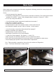
Basic Setup When setting up the components of the chair, complete the following checklist to ensure proper and safe operation of the equipment. Check : □ Are the batteries fully charged? a. Test battery voltage with D.C. meter across the terminals of batteries. The measurement should be above 12 volts D.C. (Note: a fully charged battery is between 12.9 and 13.1 VDC) b. If not, fully charge the batteries. □ Are all necessary power components installed and connected ? a. Input device (normally Joystick) b.
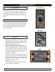
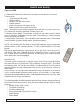
Multimeter Tutorial The Multimeter MULTIMETER For Powerchairs, the multimeter is one of the most useful tools in the toolbox. It can be used to check wires, shorts, voltages, resistance, and all manner of electrical circuits. This tutorial is designed to help clarify the symbols and socket options. The Probes Probes are found on various multimeters. The Probes connect the meter to the circuit. Simply touch them to the directed area with the Mulitmeter on the correct settings, and read the display.
Multimeter Tutorial Symbols This section describes the basic symbols used in a typical multimeter. AC ALTERNATING CURRENT Use this when you want to test something that has AC current running through it. Typically you’d want to test the voltage of an inverter (for cold cathodes or neons) or a similar device. DC DIRECT CURRENT. This is the type of electrical power produced by a battery.
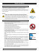
Health and Safety Good Working Practices Health and Safety While working on powered mobility products, it is essential to observe good working practices. Below are a series of safety guidelines and recommendations. Please note that these precautions are intended to serve only as a guide, not to supersede or replace any safety statute, NHS or other safety regulations. General • Always wear suitable protective clothing when handling batteries. • Always wear suitable eye protection when drilling or inspecting.
Health and Safety • Remove personal items of jewelry, such as rings, watches, chains etc. before working on batteries. Such items could cause short circuits resulting in serious burns. • Batteries are constructed of heavy materials. Therefore moving batteries requires appropriate lifting techniques. Safety footwear should also be worn. In addition, disposal of old batteries requires correct procedures. Contact your local authority for their recommendations.
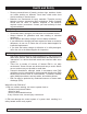
Health and Safety Sources of EMI 1. Hand-Held Transceivers: Antenna is usually mounted directly on the unit. These include: • Citizens band (CB) radios • “Walkie-talkies” • Security, fire and police radios • Cellular phones • Lap top computers with phone or fax • Other personal communication devices Note - These devices can transmit signals while they are on, even if not in use. The wheelchair should be switched off when not in use. 2.
Electro Static Discharge To help prevent Electro Static Discharge (ESD) the following proper handling techniques should be followed: ESD: • Do not place Printed Circuit Boards or their containers near sources of strong electrical fields (such as above a CRT). • To avoid the occurrence of static charge or discharge due to friction, keep the Printed Circuit Boards separate from one another and do not stack them directly on top of one another if not protected by antistatic bags.
Batteries Safety If mishandled batteries can be dangerous and hazardous. • • • • • • All mobility batteries, whether wet type or gel/sealed type, contain lead and sulfuric acid. Both of these materials are toxic and in the case of sulfuric acid, highly corrosive. Additionally, when batteries are charged, they produce hydrogen gas which is “highly” flammable and can cause explosion. This is why proper handling is mandatory at all times.
Batteries Battery Diagnostics Batteries should last an average of 1 to 1.5 years. These are some Factors that affect battery performance: • Maintenance - Poor maintenance. • Charging - Improper charging shortens battery life. • Chair Components - Malfunctioning electronics, bad motors, electric brakes, and corroded wiring are also capable of degrading the battery performance.
Batteries Battery Types IT IS THE RESPONSIBILITY OF THE INSTALLER TO KNOW WHAT KIND OF BATTERIES TO INSTALL IN A CUSTOMER’S WHEELCHAIR! • • • • Deep-cycle batteries are designed to be discharged and recharged on a regular basis. Starting or automotive type batteries use a rapid burst of power to start an engine and are quickly recharged by an alternator or generator. They are rated by cold cranking amps, a measure that has no relevance to wheelchair application.
VR2 Remote Controller VR2 Controller Buttons Battery Gauge A series of ten LED’s, which indicate charge level, and is also used for determining fault codes. On/Off Key- Press to power on or off the power chair or Controller. Horn Key- Activates a warning horn. Speed/Profile indicator- A series of five LED’s, whichdisplay speed and profile settings Speed/ Profile Decrease. Used to decrease the Speed/ Profile setting. PAGE 0.12 SEPT 2011 Speed/ Profile Increase.
VR2 Plugs/Connectors Charger Port Joystick 4pin connector 1 = 24 Vdc (POS) 1 2 4 = Red (+) 3 3 = Yellow 2 = 0 Vdc (NEG) 2 = White 3 = Inhibit 1/ Programmer 1 = Black (-) Charger port On-Board Charger - Used to power Switchcontrolled actuators and Tilt Inhibit.
R-NET Remote Controller Horn Key- Activates a warning horn. On/Off Key- Press to power on or off the power chair or Controller. Speed/ Profile Increase. Used to Increase the Speed/ Profile setting. Speed Profile Decrease. Used to decrease the Speed/ Profile setting. PAGE 0.
R-NET Remote Controller w/Display On/Off Key- Press to power on or off the power chair or Controller. Horn Key- Activates a warning horn. Speed/ Profile Increase. Speed Profile Decrease. Used to decrease the Speed/ Profile setting. SUNRISE MEDICAL Used to Increase the Speed/ Profile setting. PULSE 6 SERVICE MANUAL SEPT 2011 PAGE 0.
R-NET Plugs/Connectors Charger Port 1 2 1 = 24 Vdc (POS) 4 = Black (-) 1 2 3 = Red (+) 4 3 3 2 = Blue 2 = 0 Vdc 3 = Inhibit (NEG) 1 = White (-) On-Board Charger - Used to power Switchcontrolled actuators and Tilt Inhibit. Motor Plug Port _ + 1 = 24 Vdc 2 = 0 Vdc 3 = INHIBIT 1/ PROGRAMMER _ + Rnet Controller M1 = LEFT SIDE MOTOR M2 = RIGHT SIDE MOTOR INH-2 = INHIBIT 2 A1 = ACTUATOR 1 A2 =ACTUATOR 2 OBC = ON BOARD CHARGER + - =BATTERY PAGE 0.
Main Wiring Diagram VR2 (PLS) 4-Way Tyco Bus VR2 Hand Control Inhibit2 Inhibit3 4-Way Intech Motor 3-Way P G D C harger Power Module VR2 2-Way P G D Inhibit 2-Way PGD Actuator 4-Way Tyco Bus 4-Way Intech Motor 2-Way VR2 Intech Battery B AS E VR2 BUS SPLITTER Offboard Charger S E AT VR2 Attendant Hand Control DR IV E -T HR U HAR NE S S 4-Way Tyco Bus VR2 DRIVE-THRU SINGLE ACTUATOR 4-Way Amp Mate-N-Loc ACTUATOR ADAPTOR HARNESS 6-Way Mini-Fit J r. Switch 6-Way Mini-Fit J r.
Main Wiring Diagrams Rnet (PLS) 4-Way PGD Bus Bluetooth Modu le 4-Way PGD Bus 2-Way PGD Actuator Inhibit2 Inhibit3 4-Way Intech Motor 9-Way "D" Connector ONMI Universal Specialty Control Interface Remote Switch Option Infrared Device(s) 4-Way PGD Bus 3-Way Neutrik Charge Port 4-Way PGD Bus ACTUATOR ADAPTOR HARNESS 6-Way Mini-Fit J r.
Main Wiring Diagram VR2 and RNET (PLS6A/PLS6B) 102175 batc8ct VR2 Hand Control 4-Way Tyco Bus 4-Way Tyco Bus SEAT Offboard Charger 105375 - 4 Button 105376 - 6 Button SEAT 101626 118557-100 BASE 4-Way R-net Bus 4-Way Tyco Bus 2-Way PGD Actuator 2-Way Intech Battery Black Drive Right 104741 4-Way Intech Motor SB50 Drive Right 2-way 104742 113212 (Pulse 6) 113213 (Pulse 6) Fuse Red 104741 SB50 Fuse Red Red Black Black 113213 (Pulse 6) Black Battery Battery Battery Externa
Main Wiring Diagrams Actuators (PLS6A/PLS6B) 109230 020063-100 ACTUATOR HARNESS 3-AXIS ACTUATOR DRIVER - TILT Switch 6-Way Mini-Fit Jr. Seat Tilt 020063-160 ACTUATOR HARNESS 119131 ACTUATOR SHORTING PLUG (Use in place of tilt for legs only.) 6-Way Mini-Fit Jr. 2-Way PGD Inhibit 2-Way PGD Actuator Inhibit2 6-Way Mini-Fit Jr. Right/ Extend ELR 020063-160 6-Way ACTUATOR HARNESS Mini-Fit Jr. Left/Lift ELR 6-Way 6-Way 6-Way Mini-Fit Jr. Mini-Fit Jr. Mini-Fit Jr.
VR2 Dual Attendant System Connection 1. A s shown below, the 4 or 6 button joystick module must be connected to the short branch of the attendant module intermediate cable and the attendant joystick must be connected to the long branch. SHOR T B R A NCH L ONG B R A NCH 2. If these connections are reversed a “7-flash” communications fault will be displayed on the 4 or 6 button joystick module.
Section 1 Troubleshooting: No Power Battery Connection Test 1. Check that the female VR2 Bus plug on the chair has voltage. Set the meter to DC volts and measure pins 4 (using the red lead of the meter) and 1 (using the black lead of the meter) as shown in (fig 1.1.1) 2. If the voltage meter reads full voltage, then replace the joystick module If the voltage meter reads zero voltage measure the corresponding pins on the VR2 controller as shown in (fig 1.1.2).
Section 1 Troubleshooting: No Power (cont.) Check Battery Wire Harness Check that the battery wire harness has the correct polarity. Set the meter to dc volts and measure the connector with the red lead on the + terminal and the black lead on the negative terminal as shown in (figure 1.2.1). If the voltage is absent proceed to battery fuse test. If the polarity is reversed correct battery wiring. Fig 1.2.1 Battery Fuse Check that the battery fuse is in good condition.
Section 2 VR2 Remote Controller Display The Maximum Speed Indicator Ripples Indicates that the wheelchair is locked. To unlock the wheelchair, deflect the joystick forwards until the control system chirps. Then deflect the joystick in reverse until the control system chirps. Release the joystick, there will be a long beep. The wheelchair is now unlocked. To lock the wheelchair, while the control system is switched on, depress and hold the on/off button. After 1 second, the control system will chirp.
Section 3 VR2 Controller Diagnostic Codes One Bar - Low Battery Voltage This code could indicate discharged batteries, failed batteries, or poor battery connections. Begin by recharging the batteries and then refer to Section 1 to check batteries and connections. Fig 3.1.1 Fig 3.1.1 Two Bars - Left Motor Disconnected Check that the batteries are fully charged and in good condition; and check all cables and connections. Check the connections to the left motor, look for a loose or damaged connector.
Section 3 VR2 Controller Diagnostics Codes (cont.) Three Bars - Left Motor Wiring Trip Check that the batteries are fully charged and in good condition; and check all cables and connections. Check the connections to the left motor, look for a loose or damaged connector. Measure the resistance from the bottom contact of the red thick wire on the 4-pin left motor connector to each of the top contacts of the connector (figure 3.2.2).
Section 3 VR2 Controller Diagnostics Codes (cont.) Otherwise, check the brushes on the Right motor (figure 3.3.2). Using a Flat head screwdriver remove the brush cap to access the brush. Ensure that they are not excessively worn, see curvature on brush (figure 3.2.1) Replace as required. Fig 3.3.1 Fig 3.3.2 Five Bars - Right Motor Wiring Trip Check that the batteries are fully charged and in good condition; and check all cables and connections.
Section 3 VR2 Controller Diagnostics Codes (cont.) Six Bars - Charger Connected The Onboard Batteries are being charged with the off-board charger. You will not be able to drive the wheelchar until the charger is disconnected. You will have to reset the control system by switching off the power and then powering up again. The On-Board charger has no indication that the chair is charging, and the chair will not move until complete.
Section 3 VR2 Controller Diagnostics Codes (cont.) Nine Bars - Solenoid Brake Trip The parking brakes have a bad connection. Check the parking break and motor connections. Make sure the control system connections are secure. Measure the two small contacts on the four-pin motor connector (figure 3.5.1). If both motor connectors read approximately 60 ohms, (for chairs prior to PLS-101619 only) then replace the controller. Otherwise replace the motor that does not read approximately 60 ohms.
Section 4 R-net Troubleshooting Procedures Chair Will Not Power Up 1. Check for battery voltage at the hand control using a Multimeter. Connect the Multimeter between the two outside pins (figure 4.1.1), pin 1 is positive (+), pin 2 is negative (-). Note: Positive is on the right. 2 1 3 Fig. 4.1.1 2. If battery voltage is present, replace the following components in this order: a. Cables b. Hand control c. Control module. (refer to the Control Module Replacement section of this manual.) d.
Section 4 R-net Troubleshooting Procedures (cont.) 5. Disconnect the power connector from the control module, and use a Multimeter to check for battery voltage at the connector (figure 4.2.1). If voltage is present, replace the control module. Retest as necessary. Note: The power connector is the larger 2-pin connector between the left and right motor cable. 6. Manually tilt the seat back and remove the shroud from the base. Refer to Battery Removal section of this manual. fig 4.2.1 7.
Section 4 Rnet Troubleshooting Procedures (cont.) 9. Verify that battery voltage is present at each connector leading to the batteries (fig. 4.6). fig. 4.3.1 10. If battery voltage is not present, use a Multimeter and measure for continuity across the fusible links connected to positive (+) terminal of each battery (fig. 4.7). Normal resistance is less than 1 ohm. If open, replace the defective battery harness. Retest as necessary. . fig. 4.3.
Section 5 R-net Fault Codes Power Chair Displays a Fault on the Hand Control or Omni The R-Net control used on this power chair is constantly monitoring for conditions that can cause unsafe or erratic operation. When a fault is displayed, refer to the fault code table in this manual for a list of corrective actions. Identified Module The following identifies which module of the control system has registered the problem.
Section 5 R-net Fault Codes cont. Table 1, Error Codes cont. Over-current Overtemp. (Acts) Overtemp. (Lamps) DIME Error Memory Error PM Memory Error Bad Cable Bad Settings Module Error System Error SID Detached User Switch Detached Gone to Sleep Charging PAGE 5.2 SEPT 2011 This fault occurs when the limits of an actuator circuit is exceeded. Perform Tilt Will Not Operate troubleshooting section of this manual to test the end of travel limit switches.
Section 5 R-net Fault Codes cont. Note: On hand controls that contain LED battery gauges, they will display the fault code by illuminating various LEDs . Refer to the Corrective Action column for a list of items to check for each fault. Bar Indication Corrective Action The battery needs charging or there is a bad connection to the battery. Check the connections to the battery. If the connections are good, recharge the battery. Verify that the left motor is connected to the control module.
Section 5 R-net Fault Codes cont. Example of R-10 Fault Isolation 1. In this example, one of the right motor being disconnected (figure.5.4.1). The hand control displays the fault and the power chair will not operate. 2. To troubleshoot this problem, refer to Table 1, Error Codes. 3. From this error we see that the problem is being recorded in the PM (Control Module). 4. The hand control tells us that motor 2 (M2) has the error and it is with the brake circuit. Motor 2 is the right motor. 5.
Section 5 R-net Fault Codes cont. 3. Locate the creep micro-switch mounted at the rear of the actuator "A" (figure 5.5.1). Note: The creep micro-switch may be seen from the top of the seating system on the right rear of the actuator. It may be necessary to remove the seat pan to access the switch. 4. Manually operate the creep micro-switch while observing the hand control or Omni for the turtle symbol to go on and go off with the micro-switch operation.
Section 5 R-net Fault Codes cont. Power Chair Will Not Drive in Creep Speed When Tilted An external micro-switch is mounted next to the actuator in the rear of the tilt system. This micro-switch is open when the tilt is lowered. The opening of this micro-switch blocks a signal from being sent to the control module through the 6-pin connector located on the back of the tilt. The absence of this signal informs the control module that the tilt is less than 20 degrees and that maximum speed should be used.
Section 5 R-net Fault Codes cont. Tilt Will Not Operate The tilt actuator used in the tilt system receives power through a 6-pin connector located at the rear of the tilt See "B" (Figure 5.6.2). The actuator also contains micro-switches that open at the end of their stroke to prevent stressing of the tilt system. Around these micro switches are diodes that allow reverse power to flow to the actuator when reversing direction. 1. Select tilt on the hand control (figure. 5.7.1).
Section 5 R-net Fault Codes cont. Warning: Use caution in the next step. Do not short the leads of the Multimeter together or damage may occur to the control module. 6. At the 6-pin connector on the cable leading to the control module, verify that battery voltage is present between the indicated pins (figure 5.8.1). Note: The polarity of the voltage is not important since it is reverses when the opposite direction is selected. 7. If voltage is not present, replace the cable leading to the control module.
Section 5 R-net Fault Codes cont. Note: Since the tilt actuator will not operate, it is only possible to check for one condition. Pick the condition below that best describes the position of the tilt system. 9. Example 1, the tilt is in mid-stroke. The value recorded is the resistance through the actuator motor windings (Figure 5.9.1). If this reading is not correct, replace the tilt actuator and retest. 1 to 3 ohms fig. 5.9.
Section 5 R-net Fault Codes cont. Battery Testing The Pulse power chair uses two (2) group-22 batteries connected in series. The circuit is protected by a circuit breaker located under the shroud near the front of the power chair and a non-serviceable fusible link in each battery harness. Prior to performing any test, the battery terminals should be clean and tight. Refer to Battery Removal section of this manual. 1. Check for initial battery voltage at the joystick using the battery charger connector.
Section 5 R-net Fault Codes cont. d. Operate the power chair at high speed by operating the joystick in a high-speed profile. The motors put approximately a 5 to 10 amp load on the batteries. e. Continue to operate the motors for 60 seconds. (figure 5.11.1) Record the readings and compare them to following: i. During the first 5 seconds, normal voltage drop is approximately .5 to .6 VDC. ii. During the remaining portion of the 60 seconds, the voltage should stabilize, dropping no more than an additional .
Section 5 R-net Fault Codes cont. 3. The individual voltage of each battery may also be checked using a Multimeter. Connect the Multimeter to the battery connector (figure 5.12.1). Note: Refer to Battery Removal (Section 7). Compare the values to the following. a. 12.8 VDC indicates a fully charged battery. b. The battery readings should be similar. Newer batteries typically read within .1 to .2 VDC. c.
Section 6 Motor/Gearbox Inspection Note: This procedure may be done with or without removing the motor from the power chair. If the motor/gearbox is to be removed from the power chair, refer to Motor and Gearbox Removal, (Section7) of this manual. Consider replacing any motor/gearbox assembly that does not pass the following test. 1. Inspect the output shafts for signs of grease leakage (figure. 6.1.1). fig. 6.1.1 2. Inspect the cotter pin connecting the gearbox release arm to the motor/gearbox assembly.
Section 6 Motor/gear Box Inspection (cont.) Note: When replacing brush assemblies, always replace both motors. Run-in the brush assemblies prior to delivering the power chair to the customer by releasing the gearbox assembly and operating the motor for 20 to 30 minutes, alternating between forward and reverse. 5. Inspect the brush assembly (figure. 6.2.1). Replace any brush assembly less than ¼ inch long.
Section 6 Motor/gear Box Inspection (cont.) 8. Measure the resistance of the park brake assembly by connecting a Multimeter to the small pins of the 4-pin connector (figure. 6.3.1). Normal resistance is approximately 12 to 15 ohms. fig. 6.3.1 9. Measure the resistance through the motor brush assembly and motor by connecting a Multimeter to the large pins of the 4-pin connector (figure. 6.3.2). Normal resistance is approximately .5 to .9 ohms.
Section 7 Removal Procedures Battery Removal 1. Remove the two thumb screws under the front of the seat (figure. 7.1.1) fig. 7.1.1 2. Inspect the power chair base at the back and disconnect any connectors that may be damaged before tilting the seat back (figure 7.1.2). fig. 7.1.2 3. Flip back the arms to prevent damage to the arms as the seat back is tilted (figure 7.1.3). fig. 7.1.3 SUNRISE MEDICAL PULSE 6 SERVICE MANUAL SEPT 2011 PAGE 7.
Section 7 Removal Procedures (cont) Caution: While not required, it may be a good idea to place a box under the seat back prior to tilting the seat. 4. Tilt the seat back while ensuring that none of the cables attached to the electronics are damaged (figure 7.2.1). fig. 7.2.1 5. Locate and remove the 6 plastic inserts that secure the shroud to the base (figure 7.2.2). Effective on chairs with s/n prefix PLS only. fig. 7.2.2 6.
Section 7 Removal Procedures (cont.) 7. Locate the two batteries mounted in the base (figure 7.3.1) Note the battery connectors. fig. 7.3.1 8. Disconnect the battery connectors (figure 7.3.2). 8. Remove the batteries. 9. Replace the batteries by reversing the previous procedures. fig. 7.3.2 Battery Installation Batteries installed incorrectly can blow the fuse for this system. Pay careful attention to install the battery harness across both batteries instead of to each of the batteries individually.
Section 7 Removal Procedures (cont.) Motor and Gearbox Removal 1. Remove the batteries. Refer to the Battery Removal in this section. 2. Locate and disengage the connector leading from the motor to the control module (figure.. 7.4.1). fig. 7.4.1 3. Elevate the wheelchair by placing wood blocks under the battery box (fig. 7.4.2). fig. 7.4.2 4. Remove the wheel’s hubcap by prying it off using a common screw drive (figure. 7.4.3) . fig. 7.4.3 5.
Section 7 Removal Procedures (cont.) 6. Use 17 mm Rachet and 17 mm open end to remove bolt ,locknut and washer from frame (figure 7.5.1). fig. 7.5.1 7. View of 17mm nylock nut (figure 7.5.2). Slide Motor Assembly down and out of frame. fig. 7.5.2 8. Effective for chairs prior to PLS-101619 only. With the motor removed from the chair, use a 3mm or 1/8" pin punch to drive out the spring pin (figure 7.5.3). 9.
Section 7 Motor Removal for chairs after S/N PLS-101919 and s/n prefix PLS6A &PLS6B 1. Remove 4 bolts from wheel and elevate frame as shown. (Figure 7.6.1) fig. 7.6.1 2. Using a 17mm socket and open end wrench, remove front suspension bolt and nut combination shown in (figure 7.6.2) fig. 7.6.2 3. Remove motor from chair (figure 7.6.3) fig. 7.6.3 4. Remove the 5 bolts from the motor plate assembly with a 5mm Hex Key (figure 7.6.
Section 7 Removal Procedures (cont.) Control Module Removal 1. Remove the rear cover by lifting the two quick release pins from the cover (figure. 7.7.1). fig. 7.7.1 Note: The control module is mounted under the rear cover of the power chair (figure 7.7.2). fig. 7.7.2 2. Carefully disconnect the connectors leading to the control module (figure 7.7.3) fig. 7.7.3 SUNRISE MEDICAL PULSE 6 SERVICE MANUAL SEPT 2011 PAGE 7.
Section 7 Removal Procedures (cont.) 3. Loosen the control module by loosening two 3 mm Allen screws (figure 7.8.1). Note: It may be necessary to remove the batteries to gain access to the nuts on the other side of the control module. fig. 7.8.1 4. Slide the control module up to remove it (figure. 7.8.2). 5. Reverse the above procedures to install the control module fig. 7.8.2 PAGE 7.
Section 7 Removal Procedures (cont.) Shock Removal NOTE: The shocks used in this power base are pre-adjusted at the factory. Contact Sunrise Medical Technical Service if adjustment is required. 1. Remove the batteries. Refer to the Battery Removal section. 2. Remove the motor/gearbox assembly from the side on which you are removing the shock. Refer to Motor/Gearbox Removal section of this manual. fig. 7.9.1 3. Use a 17 mm wrench and remove the top bolt securing the shock to the base (figure 7.9.1). 4.
Section 7 Removal Procedures (cont.) Front Caster Arm Removal 1. Remove the batteries. Refer to the Battery Removal section of this manual. 2. Remove the motor/gearbox assembly. Refer to the Motor/Gearbox Removal section of this manual. 3. Remove the two braces connecting the front caster arm to the rear caster arm using 19 mm wrenches (figures 7.10.1 & 7.10.2). fig. 7.10.1 fig. 7.10.2 4. Remove the coupler that connects to the two braces (figure 7.10.3). fig. 7.10.3 PAGE 7.
Section 7 Removal Procedures (cont.) 5. Push down on the rear of the motor mount assembly to allow clearance for the front caster arm assembly to slide out (figure 7.11.1). fig. 7.11.1 6. Remove the front caster arm assembly. (figure 7.11.2) 7. Reverse the previous procedures to install the front caster arm assembly. fig. 7.11.2 SUNRISE MEDICAL PULSE 6 SERVICE MANUAL SEPT 2011 PAGE 7.
Section 7 Removal Procedures (cont.) Rear Caster Arm Removal 1. Remove the batteries. Refer to the Battery Removal section of this manual. 2. Remove the two braces connecting the front caster arm to the rear caster arm using 19 mm wrenches. (figure 7.12.1 & 7.12.2) fig. 7.12.1 3. Remove the rear caster arm assembly (figure 7.12.3). fig. 7.12.2 4. Reverse the previous procedures to install the rear caster arm assembly fig. 7.12.3 PAGE 7.
Section 7 Removal Procedures (cont.) Front or Rear Caster Fork Removal 1. Elevate the caster fork to be removed by placing wood blocks under the battery box of the power chair (figure 7.13.1). fig. 7.13.1 2. Remove the plastic cap on the caster arm assembly using a common screwdriver (fig. 7.13.2). fig. 7.13.2 3. Hold the caster steady with one hand while removing the caster fork nut with a 19 mm socket wrench (fig. 7.13.3). 4. Remove the caster fork from the caster arm assembly (fig. 7.13.4) fig. 7.
Section 7 Removal Procedures (cont.) Caster Removal 1. Elevate the caster fork to be removed by placing wood blocks under the battery box of the power chair (figure 7.14.1). fig. 7.14.1 2. Remove the caster using two 13 mm wrenches (figure 7.14.2). fig. 7.14.2 3. Reverse the previous procedures to install the caster (figure 7.14.3). fig. 7.14.3 PAGE 7.
Section 7 Removal Procedures (cont.) Tilt Actuator and Micro-Switch Removal The following procedures describe the removal of the tilt actuator and/or the micro-switch assembly used for the creep speed. Read the full set of directions prior to performing the task. Some steps may be eliminated if both items do not need to be replaced. Reverse the procedures to install the tilt actuator and/or micro-switch and retest as necessary. A 1.
Section 7 Removal Procedures (cont.) Note: Complete step 4 only if the micro-switch assembly is to be replaced separately. 4. Reconnect the 6-pin connector on the rear of the tilt and partially tilt the seating system back to expose the actuator. Disconnect the 6-pin connector 5. Locate the tilt actuator under the seat (figure 7.16.1). fig. 7.16.1 6. Locate the micro-switch assembly at the rear of the tilt (figure 7.16.2). Note the connections leading to the micro-switch.
Section 7 Removal Procedures (cont.) Caution: the actuator and micro-switch assembly wires are fragile. Use caution when removing the actuator and micro-switch assembly. 8. Remove the actuator and micro-switch assembly as one part if the entire assembly is to be replaced (figure 7.17.1). Reverse the procedures to install and retest as necessary. fig. 7.17.1 Note: Perform this step if only the actuator is to be replaced. 9. Note the connections of the wires and separate them (figure 7.17.2).
Section 8 Seat/Back Width adjustment ASAP II Seating 16” - 20” wide is shown. (NOTE: The same procedure is used for 18”- 22” wide seating system) The ASAP II seating system is fully adjustable to allow changes from 16” to 20” or 18” – 22”. This requires a frame weldment and seat pan plates adjust for seat growth. The pictures shown in (figure 8.1.1) shows a 20” wide seat width . This detail shows how easy it is to change back to 16” wide. A To make seating width adjustments follow the following steps: 1.
Section 8 Seat/Back Width adjustment 5. Remove the nut, and bolt that secures the rear towel bar using a 4mm Hex Key and a 13 mm open end wrench or ratchet as shown in (figure 8.2.1). fig. 8.2.1 6. Loosen Back bracket on the chair to allow for changes to the seat width. (figure 8.2.2). NOTE: it is recommended to use the back width to accommodate the user, for example – so 16 with 16 wide – 18 with 18” wide. If, however there is a ½ “ adjustment that is needed, the brackets shown in (figure 8.2.
Section 8 Seat/Back width adjustment 8. After checking alignment and symmetry of the final adjustments, and measuring (figure 8.3.1) the final adjustment change, the nuts and bolts can be re-tightened in the reverse order of the steps listed. Make sure all bolts are tightened to appropriate Specifications. SUNRISE MEDICAL PULSE 6 SERVICE MANUAL SEPT 2011 PAGE 8.
Section 8 Legrest adjustment 1. To perform a Legrest adjustment (figure 8.4.1) the following tools are required: A 5mm Hex Key, and a 13mm open end wrench and/or ratchet. fig. 8.4.1 2 Loosen all 3 sets of bolts/nuts as shown in (figure 8.4.2) and (figure 8.4.3) using the 5mm hex key and 13mm open-end wrench or ratchet. fig. 8.4.2 3. There are 5 sets of holes as seen from the front bars and 6 sets of holes as seen on on (figure 8.4.
Section 8 Back-rest Angle Adjustment 1 Make sure you have the right tools- 5mm Hex Key, and 13mm open end wrench and/or ratchet. A 2. Loosen the 2 BHCS bolts "A" (figure 8.5.1) with a 5mm Hex key and use 13mm open end Wrench for the nuts "B". B fig. 8.5.1 Note: Take care not to lose the saddles, or plastic washers between Bracket and seat rail while performing the next step. -4° 3.
Section 8 Powered elevating or articulating legrest VR2/R-Net Control The actuator buttons can operate any factory approved actuator. Operation is dependent on what options are fitted to your wheelchair. To operate the legrests, seat tilt, seat lift or back rest recline follow the following steps 1. Push one of the actuator buttons that has the seat icon on it to select actuator mode 2 Operate the joystick left or right to select the actuator required (actuator 1 or actuator 2).