
Operating instructions

108833 Rev. C
16
S-636 / S-646
IX. SET-UP, ADJUSTMENT, & USE
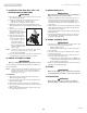
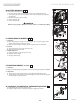
H. REMOTE JOYSTICK SWING-AWAY RETRACTABLE MOUNT
(OPTIONAL)
The remote joystick is mounted with a mechanism which allows the control to be locked in a
forward or retracted position using magnets.
a) To retract joystick, push outward on side of joystick.
b
) Push joystick away from front of armrest until it locks into retracted position.
c) To return to forward position push joystick forward until it locks into place.
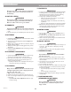
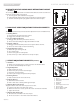
I. DUAL-POST HEIGHT-ADJUSTABLE FLIP-BACK ARMRESTS
The dual-post flip-back armrest can be used as either a flip-back armrest or a removable armrest.
1. Installing Armrest
a) Insert front and rear posts into armrest receivers.
b) Engage levers (A and B) to secure armrest.
2. Set-up for Flip-back Operation
a) Disengage lever (A) so front post is able to come free.
b) Armrest now has the ability to be flipped back without removal.
3. Removal of Armrest
a) Disengage both levers (A and B) so front and rear post are able to come free.
b) Armrest can now be easily removed for transferring.
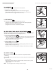
4. Height Adjustment (option)
a) Release the upper securing lever (C).
b) Set at desired height.
c) Return securing lever to locked position.
d) Move armrest up or down to allow armrest to snap into place.
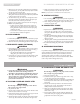
J. HEIGHT-ADJUSTABLE ARMRESTS (OPTIONAL)
1. Installation
a) Slide the outer armpost into the receiver mounted to the wheelchair frame.
b) The armrest will automatically lock into place.
2. Height Adjustment
a) Rotate release lever to stop.
b) Slide armrest pad up or down to desired height.
c) Return lever to locked position.
d) Push arm pad until upper armpost locks firmly into place.
3. Removing Armrest
a) Rotate release lever and remove the armrest.
4. Replacing Armrest
a) Slide armrest back into receiver.
b) Return release lever to locked position against armpost.
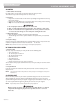
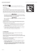
5. Adjusting Armrest Receiver Fit
To tighten or loosen the fit of the outer armpost in the receiver:
a) Loosen the four bolts on the sides of the receiver.
b) With the armrest in the receiver, squeeze the receiver to achieve the desired fit.
c) Tighten the four bolts.
6. Adjusting Inner Armpost Fit
a) Two set screws are installed in the outer armpost.
b) Turn the set screws in or out until the desired fit is achieved.
7
8 9
10
A
B
7
8
C
9
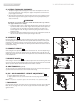
1. Inner Arm Post
2. Receiver
3. Release Lever, Locked Position
4. Armrest Pad
5. Transfer Bar
6. Side Panel
7. Tension Adjustment Set Screw
8. Outer Arm Post
9. Receiver Adjustment Bolts
10. Receiver Release Lever
1
2
3
4
5
6
7
8
9
10
10