Instructions for Use Salsa & Salsa M
User Information Intended use power wheel chairs: Power wheelchairs are exclusively for a user who is unable to walk or has limited mobility, for their own personal use in- and outdoor. When an Attendant Control Module is fitted, the Power Wheelchair may be operated by an assistant on behalf of the user. When a Dual Control Module is fitted the Power Wheelchair may be operated by the user, or control may be switched to an assistant to operate on behalf of the user.
6.7 Seat width adjustment 6.8 Seat Depth Adjustment 6.9 Backrest Angle Adjustment 6.10 Back Height Adjustment 6.11 Manual adjustable backrest (manual recline) 6.12 Manual setting the seat angle on the SALSA 6.13 Headrest 6.14 Powered Seating 31 32 32 33 35 35 36 36 7.0 The VR2 Hand Control Series (Fig.7.1) 7.1 VR2 7.2 VR2-L 7.3 VR2 Dual control unit 38 38 40 41 8.0 Troubleshooting using VR2 Hand Control 43 9.0 Controller Mounts 45 10.
SALSA Armrest Controller Cushion Legrest Drive wheel Footplate Castor Backrest Skirt Guard Batteries Anti-tips 4 SALSA M
SALSA M Armrest Controller Cushion Legrest Drive wheel Footplate Front castor Backrest Skirt Guard Batteries Rear castor SALSA M 5
1.0 Your Wheelchair 2.0 How to use this manual We at Sunrise Medical want you to get the best out of your SALSA wheelchair. This Owner’s Manual will familiarise you with the chair and its features. It contains hints on everyday usage and general care in addition to information on the high quality standards which we adhere to and details about the guarantee. 2.1 Introduction Please keep a note of your local service agent’s address and telephone number in the space below.
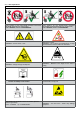
4) Any repaired or replaced part will benefit from these arrangements for the balance of the warranty period applicable to the wheelchair. 3.0 Label Explantation / Word definitions 3.1 Definitions of words used in this manual 5) Parts replaced after the original warranty has expired are covered for a further twelve months.
3.2 Label explanations Labels and their descriptions Lever position for the LEFT-HAND freewheel mechanism SALSA M (& SALSA from August 2010). Tick = IN DRIVE, Cross = IN FREEWHEEL Lever position for the RIGHT-HAND freewheel mechanism SALSA M (& SALSA from August 2010).
Labels and their descriptions Battery Label – Warning Instructions and Circuit Diagram Back Rest Recline Seat Lift Seat Tilt in Space The power Tilt and power Lift/Tilt modules are factory fitted for optimum stability and for conformance to strict standard requirements.
4.0 General safety warning and user tips 4.1 General warnings WARNING! • • • • • • • Always ensure that your wheelchair is switched off before attempting to transfer in or out. Always ensure that you are able to operate all controls from a comfortable position. Paying attention to your posture is essential to ensure your continued comfort and well being. Always make sure that you can be seen clearly, especially if you intend using your wheelchair in poor light.
4.6 EMC - Radio transmitting devices. WARNING! When operating two-way radio, walkie-talkies, C.B., amateur radio, public mobile radio and other powerful transmitting devices the wheelchair should be brought to a halt and turned off. The operation of cordless, mobile telephones and cell phones including hands-free devices is permitted but if abnormal operation of the wheelchair is encountered then the chair must be brought immediately to a halt and turned off.
4.11 Weight limit DANGER! • • • • The user plus items carried should never exceed a total weight of 140Kg. Never use this chair for weight training if the total weight (user plus additional weights) exceed a total weight of 140Kg. Exceeding the weight limit is likely to damage the seat, frame or fasteners and may cause severe injury to you or others from chair failure Exceeding the weight limit will void the warranty. 4.
4.16 Adverse conditions Please be aware that when driving your wheelchair in adverse conditions, e.g. on wet grass, mud, ice, snow or other slippery surfaces, you may experience a reduction in the grip and traction of your wheelchair. WARNING! We recommend you take extra precautions in these conditions, particularly on hills and slopes; your wheelchair could become unstable or skid causing possible injury. NOTE: Extreme variances in temperature may trigger the self protect mechanism in the control system.
4.20 Anti-tips 4.21.2 Gradients: descents WARNING! • WARNING! Make sure that anti-tips are not damaged or worn before using your chair. Attendants must be aware of the location of the antitips to prevent feet being trapped underneath causing injury. Attendants - Do not stand on the anti-tips, this could cause the wheelchair to become unstable. On descents, it is important not to let the wheelchair accelerate beyond its normal level of ground speed.
4.23 Creep mode WARNING! Please ensure your backrest recline angle relative to floor level, which is a combination of the back recline itself and the tilt angle, does not exceed 12° to drive the chair safely. NOTE: If the tilt angle exceeds 9° the chair will the chair will automatically convert into “creep mode” which will allow you a maximum of 10% of the speed programmed in the profile.
4.26 Rear view mirror WARNING! To avoid injury to people around you please be aware that the mirror protrudes outside the space envelope of the chair and could cause injury to someone when driving past. The mirror must be used on the 10KPH model on UK roads. Always make sure that when using the mirror that it is clean and unbroken so that it does not impair your visibility. 4.27 Crutch holder WARNING! • • • • • Make sure that the crutch is securely fastened to the crutch holder.
Salsa M (MWD) Approach the kerb in a 90° angle and stop the chair as soon as the castor wheels touch the kerb. Apply sufficient power to the motors to lift the front of the chair up onto the kerb (step) and then apply slightly more power and speed so that the drive wheels climb the kerb (step) smoothly and without hesitation and the rear castor wheels come up as well. As far as possible, keep the joystick in the straight forward position, (Fig.4.10 - 4.11). Fig. 4.10 Fig. 4.11 WARNINGS! 1.
4.31 Lap belt 4.32 VR2 Controller (Fig. 4.21) The lap belt kit. (Fig. 4.14). Fastening the lap strap: Insert the 3 prong male buckle into the female buckle until a click is heard (Fig. 4.15) To fit the lap strap. Place the strap loosely across the seat with the buckle closed.. (Fig. 4.16) Pass the other ends of the strap through the gap between the backrest posts and the backrest upholstery as shown. (Fig. 4.17) Ensure that the adjusters & buckles can be accessed & the strap is not twisted.
5 Preparing your wheelchair for use 5.1 Handling the wheelchair Note: To dismantle the chair for transport or storage no tools are required. List of components when dismantled (components below are related to the maximum detachable parts and dependent on the type of seating system chosen): 1 pair of armrests 1 pair of legrests 1 backrest 1 drive unit with seat frame 5.2 Preparation for transportation or storage First remove the swing-away legrests. Leave the armrests in the fold down position. (Fig.5.1).
5.3 Re-Assembling Replace the backrest into the receivers and tighten the lever screws carefully. If required reconnect the remote controller. Attach the hangers. Make sure your freewheel mechanisms are engaged. Now you are ready to drive the chair. SALSA M (& SALSA from August 2010, Fig. 5.12 & 5.13) By rotating the red lever outwards on both sides of the motor the brakes are released from the motors.
DANGER! The LPFDR should only be used with a user in the powerchair in Emergency situations as the automatic brakes will become inoperable. DANGER! The automatic brakes become inoperative when the Brake release, or LPFDR is disengaged allowing the power chair to run free if left on an incline. DANGER! 5.5 Drive wheel suspension Salsa The SALSA M/R has an effective and adjustable drive wheel suspension system as a standard feature.
5.8 Armrests 5.8.1 Armrests-removing and replacing The armrests on both sides of the wheelchair can be flipped up to allow side transfer, (Fig. 5.18). For side transfer flip the armrest all the way up until it goes into its mechanical stop. This frees your space for side transfer. To bring the armrests back into their position flip it all the way down until it sits on its mechanical stop. Guide it in its downward movement and do not let it fall on its own. Fig. 5.19 Fig. 5.18 5.8.
2.Basic coarse adjustment. PART 1 1. To achieve more than one inch of adjustment, remove the 6mm armrest rotation bolts on both sides of the seat, (Fig.5.23). 2. Remove both armrest assemblies. (Fig.5.24) 3. Remove both sets of 4mm armrest adjustment ring bolts.(Fig.5.25) 4. Rotate the armrest height adjustment rings, (Fig.5.26) to match the desired height designated in the Configuration Chart, (Fig.5.35), on page 25. 5.
PART 2 1. Loosen the 4mm arm pad angle pivot bolts (A) on both armrests. Remove the 4mm angle index bolts (B) on both armrests, (Fig.5.30). 2. Use the 5mm fine height adjustment screw (B) to finish fine tuning the height. Turn counter-clockwise to increase height or clockwise to lower, (Fig.5.31). 3. Tilt both arm pads down, (or up in the case of a lowered armrest), until the arm pads are in the preferred angle. Check to see if the height is correct, (Fig.5.32). 4. Refer to 2 for fine adjustment. 5.
A POSITION A B POSITION B C POSITION C CONFIGURATION CHART BACKREST ANGLE (Degrees) ARMREST HEIGHT (mm) SETTING RING POSITION -4 305 - 254 A -4 252 - 229 B 0 305 - 254 A 0 252 - 229 B 4 305 - 267 A 4 279 - 229 B 8 305 - 229 B 12 305 - 229 B 12 248 - 229 C 16 305 - 254 B 16 260 - 229 C Fig. 5.
5.8.3 1. Arm pad Position Adjustment (Fig. 45 - 48) Fine arm pad position adjustments (one to two inches) are possible by loosening the 4mm arm pad adjustment bolts (E) and sliding the arm pad forward or backward as required, (Fig.5.36, 5.37). Access to the rear adjustment bolt may require pivoting the arm pad 2. Retighten both adjustment bolts (E). Use 10 N/m or 88.5 in/lb of torque, (Fig.5.38). NOTE: If more than one to two inches of adjustment is required, refer to chart below, (Fig.5.39). Fig. 5.
NOTE: The internal footrest stem may require cutting down in length to allow the footplate position to be raised. 5.9 Legrests WARNING! Be aware of your environment to make sure you do not injure your legs when legrests are extended. SCREWS WARNING! Always ensure that the legrests or footplates do not come into contact with the castors before driving the wheelchair. WARNING! Legrests are not to be used for lifting or carrying the wheelchair with an occupant. 5.9.
5.9.5 ELR) Manual Articulating / Elevating Legrest (ALR/ 5.9.6 Powered Elevating or Articulating Legrest (Fig. 5.47) To elevate: Pull the legrest upwards and stop at the desired height. The legrest will automatically lock in the chosen position. NOTE: Both legrests can be operated simultaneously. To lower: Push the release lever slowly forward. The legrest will lower the angle. As soon as you release the lever, the legrest will be locked in the current position, (Fig.5.46).
Quickie Direct Actuator Control Box: The direct actuator switches can operate any factory approved actuator. Operation is dependent on what options are fitted to your wheelchair. To operate the legrest, seat tilt, seat lift or backrest recline; • • Push the toggle switch for the relevant actuator forward until you reach the required angle/height. Release the toggle switch and the actuator will stop.
6 Seating Fig. 6.1 6.1 Firm seat board The firm seat board is designed to allow pressure relief cushions such as Jay to be used. 6.2 Seat cushions Seat cushions supplied by Sunrise Medical will have Velcro® strips that correspond to patches on the seat. You must ensure these are aligned prior to using the wheelchair. Other cushions used should also have Velcro® strips in a similar position to ensure the cushion does not slip off the seat.
6.6 Seat height adjustment WARNING! Fig. 6.6 Make sure the top frame does not trap your fingers. Get someone to hold the seat steady during adjustment. To change the seat height: Salsa Rear Wheel Drive only: • Remove the two bolts from the front seat posts, using a 5mm allen key. • Access the bolts by removing the front cover. • Take the safety clips off the flat rear posts, pull the ring pins out and loosen the two clamping bolts.
3. Move the right side seat rail , armrest and backrest assembly to the desired position. Replicate position settings used for the left side, (Fig.6.9). 2. Slide the rear backrest and armrests into the desired seat depth position. Reference seat depth position patterns (A), (Fig.6.12). Fig. 6.12 Fig. 6.9 4. Replace the width adjustment bolts (A) and the towel bar adjustment bolt (B). (Use 10 N/m or 88.5 in/lb of torque for A and B.), (Fig.6.10). 3. Replace both sets of depth adjustment bolts.
2. Tilt the backrest assembly forward or backward to the desired angle. See angle configurations below, (Fig.6.15). Fig. 6.15 6.10 Back Height Adjustment 1. Begin by removing the upholstery cover, (Fig.6.17). Fig. 6.17 2. Loosen the upholstery straps. It is not necessary to remove the upholstery, (Fig.6.18). Fig. 6.18 3. Remove the top upholstery screws. The upholstery can now be moved and vertically compressed to provide access to the hidden Phillips-head bolts, (Fig.6.19). Fig. 6.19 3.
4. Remove the 4mm towel bar bolts and the towel bar, (Fig.6.20). NOTE: This step is not necessary in every case. If the push handles are high enough, the towel bar bolts might not thread into the push handle tubes. To test, skip this step and move to Numbers 5 and 6. If the towel bar does not impede movement of the push handles, the towel bar may be left intact. 7. Replace the backpost adjustment screws. Use 10 N/m or 88.5 in/lb of torque, (Fig.6.23). Fig. 6.23 Fig. 6.20 8.
10. Retighten the upholstery straps, (Fig.6.26). Fig. 6.26 6.12 Manual setting of the seat angle on the SALSA To set the seat angle, release the bolt fixing the “Banana” bracket between the seat interface module and the seat packer module. Set the seat angle at 0°, 3° or 6° and 9°, then replace and retighten the bolt between the seat interface module and the seat packer module. (Fig.6.29). Fig. 6.29 11. Reattach the upholstery cover, (Fig.6.27). Fig. 6.27 0° 6.
6.13 Headrest To fit the headrest, fit the location bracket to the push handles, using the screws and nuts supplied, ensuring that they are fully tightened. The headrest height is changed by loosening the adjustment knob and sliding the inner vertical tube to the desired position and tightening the knob. The headrest to seat depth is adjusted by loosening the 6mm Allen screws and moving the hinge to the desired position and then tightening the screws securely.
CAUTION! Once the back is fully reclined/forward, or the lift is fully raised/lowered, or the seat is fully tilted backwards/ forwards, do not continue to hold the joystick in its operating position as this could damage the actuator. Fig. 6.32 QUICKIE DIRECT ACTUATOR CONTROL BOX (Fig.6.32) To operate the backrest, seat lift, seat tilt: • Push the relevant toggle switch into the forward position. • Release the toggle switch when the desired backrest angle, seat lift height or seat tilt angle is reached.
7.0 The VR2 Hand Control Series (Fig.7.1) 7.1 VR2 On/off button: The on/off button applies power to the control system electronics, which in turn supply power to the wheelchairs motors. CAUTION! Do not use the on/off button to stop the wheelchair unless there is an emergency. (If you do you may shorten the life of the wheelchair drive components) Battery gauge: The battery gauge shows you that the wheelchair is switched on. It also indicates the status of the wheelchair. Refer to chapter 8.
The horn button: The horn will sound while this button is depressed. Speed / Profile decrease button: This button decreases the maximum speed setting or, if the control system is programmed for drive profile operation, selects a lower drive profile. Speed / Profile increase button: This button increases the maximum speed setting or, if the control system is programmed for drive profile operation, selects a higher drive profile.
7.2 VR2-L There are common controls between the VR2 and the VR2-L control systems where a control differs it will be described below. All common controls can be found on the previous page. Lights and indicators: The SALSA can be equipped with lights and indicators. Where lights are not factory fitted, they may be fitted as an optional extra by an approved Sunrise Medical authorised dealer.
7.3 VR2 Dual control unit Maximum speed button and indicator: Control button and indicator: This shows which joystick has control. If the red wheelchair light is on the wheelchair occupants joystick has control. If the green attendant light is on the dual attendant systems joystick has control. The button is used to transfer control between the two choices when the dual attendant system has control. There are five settings - setting 1 is the slowest speed and setting 5 is the highest speed.
Fig.7.1 JOYSTICK CONTROL PANEL CHARGER & PROGRAMMING SOCKET BATTERY GAUGE HAZARDS BUTTON ON-OFF BUTTON LIGHTS BUTTON MAX. SPEED/ PROFILE INDICATION HORN BUTTON ACTUATOR BUTTON SPEED/ PROFILE INCREASE BUTTON SPEED/PROFILE DECREASE BUTTON VR2 CONTROL PANEL LAYOUT JOYSTICK INDICATOR BUTTONS VR2-L CONTROL PANEL LAYOUT SPEED INDICATOR MAX.
8 Troubleshooting using the VR2 Hand Control WARNING! Always consult your Sunrise Medical authorised dealer when a diagnostic fault has appeared on your hand control. The battery gauge and maximum speed/profile indicator show the status of the control system. Battery Gauge is steady: This indicates that everything is OK. Battery Gauge flashes slowly: The control system is functioning correctly but the batteries need charging as soon as possible.
Self Help Guide, (Fig.8.1). Fault code Possible cause Fig.8.1 The batteries need charging, or there is a bad connection to the battery. Check the connections to the battery. If the connections are good, try charging the batteries The left hand motor has a bad connection. Check the connections to the left hand motor. The left hand motor has a short circuit to a battery connection. Contact your Sunrise Medical Authorised Dealer The right hand motor has a bad connection.
9 Controller Mounts 9.3 9.1 General warnings: WARNINGS! WARNINGS! • • • 9.2 • Do not replace the joystick knob with any unauthorised item. It may cause hazardous operation and loss of control of the chair. It is important that the joystick boot is replaced if it is torn or brittle; failure to do so could cause substance damage to the controller and unexpected movement of the chair.
10 Batteries and charging Fig.10.1 WARNING! Please read the owner’s manual supplied with the charger carefully. WARNING! Do not expose any part of the battery to direct heat (i.e. naked flame, gas fire). WARNING! When charging always place your charger on a hard surface in a room with good ventilation. Fig.10.2 WARNING! You should not charge your batteries in outdoor conditions. 10.1 Batteries Salsa (Fig. 10.1 - 10.5) The batteries are contained within the drive unit located under the battery shroud.
10.1.1 Batteries Salsa M (Fig. 10.6 - 10.12) The batteries are contained within the drive unit located under the battery shroud. To remove the batteries: • Release the two handle screws under the front of the seat frame that connect the seat frame with the seat module interface. • Release and hold the safety locking pin. • Flip the seat frame backwards and secure it with the safety bar, (like the bonnet of a car). • Ensure the plastic cap is pushed over the tube to secure the safety bar.
10.2 Safety cut-outs In the event of a short circuit there are several safety systems built into your wheelchair to safeguard your electrical circuits. • • • Fusible 150A links are connected into the battery harnesses to protect the batteries and wiring. A 70A re sett fuse. This is located on the front left side of the battery compartment. A 15A fusible link. (When Quickie Direct Actuator Control Box is fitted or other modules requiring auxiliary power). This is located behind the front shroud.
10.7 General charger information The external charger has been designed to charge two 12V Gel type batteries connected in series (= 24 V). Fig.10.13 10.8 Charger safety features The chargers have features which prevent hazards or accidents occurring as a result of connecting batteries the wrong way round, overheating caused by fault conditions or attempting to charge wrong voltage batteries. The majority of charger sizes are electrically double insulated and no earth connection is required.
10.11 The range of your vehicle Most manufacturers of mobility products state the range of their vehicles either in the sales literature or within the Owner’s Manual. The range stated sometimes differs from manufacturer to manufacturer even though the battery size is the same. Sunrise Medical measure the range of their vehicles in a consistent and uniform manner, but variances still occur due to motor efficiencies and overall product load weight. The range figures are calculated to I.S.O. Standard 7176.
WARNINGS! • • • • • • • • • • • • • • An extension cord should not be used unless absolutely necessary. Use of an improper extension cord could result in a risk of fire and electric shock. If any extension cord must be used, make sure the pins on the plug of the extension cord are the same number, size and shape as those of the plug on the charger; and that the extension cord is properly wired and in good electrical condition. Do not rest a battery on top of the charger.
11 Transportation WARNINGS! A wheelchair secured in a vehicle will not provide the equivalent level of safety and security of a vehicle seating system. Sunrise Medical recommends that the user transfers to the vehicle seating and uses the vehicleinstalled restraint system wherever possible.
11.2 • • • • • • WARNINGS! Occupant restraint instructions WARNINGS! • The pelvic restraint belt must be worn low across the front of the pelvis (Fig 11.2) so that the angle of the pelvic belt is within the preferred zone of 30° to 75° to the horizontal, (Fig 11.3). A steeper (greater) angle within the preferred zone is desirable i.e. closer to, but never exceeding 75°. Restraint belts must not be held away from the body by wheelchair components or parts such as the armrests or wheels, (Fig 11.4).
11.3 Crash testing on the SALSA A representative SALSA & SALSA M wheelchair has been tested in accordance with the dynamic performance requirements specified in ISO 7176-19:2001 “Wheeled Mobility Devices for use in Motor Vehicles” using a Q straint 6 point strap restraint system with double straps at the rear which conform to ISO 10542 or SAE J2249 and was used in accordance with the WTORS manufacturer’s instructions. The Q straint restraint system was used for these tests.
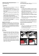
11.5 Securing the wheelchair into the vehicle (Fig. 11.11 - 11.16) Fig.11.13 WARNING! The SALSA wheelchairs (RWD/MWD) require a sixpoint tie down system for transportation as shown in the photographs. On the left rear side: • Use one of the rear tie down restraints, attach it as close as possible on the left rear mounting bracket to an angle of 45°, and tighten securely in accordance with the restraint manufacturers’ instructions.
12 Maintenance and Cleaning 12.3 Drive wheel tyre repair WARNING! CAUTION! It is important that you follow the following cleaning and maintenance schedule in order to keep your wheelchair in tip top condition. Wheel removal and tyre changing is a safety critical task. If you do not feel confident in carrying out the following instructions, please contact your Sunrise Medical Approved Dealer. 12.
Fig.12.1 Fig.12.5 Fig.12.2 Fig.12.6 Fig.12.3 Fig.12.7 Fig.12.4 Fig.12.
Fig.12.9 12.4 Removing the castor wheel WARNING! Castor wheel removal is a safety critical task. If you do not feel confident in carrying out the following instructions, please contact your Sunrise Medical Approved Dealer. • • • Fig.12.10 • • • • • • • • 58 Note which one of the two holes is used to mount the castor wheel. Ensure that both castors use the same mount position. Depending on the castor wheel type use two 5 mm hex keys or two 13 mm spanners to undo the axle bolt, (Fig.12.13 & 12.14).
Fig.12.15 12.6 Inspection of the upholstery/seating Tears, dents, wearing or slackening of upholstery particularly near to metal could result in poor posture or lower levels of comfort and pressure relief. 12.7 Cleaning seating • You can wash all parts of the covers with a gentlewash detergent at 40°C. • You can spin-dry the covers. CAUTION! Do not dry the covers in a dryer. • Fig.12.16 • • • You can remove all parts of the covers independently of each other and wash them separately.
12.8 Cleaning controls Clean the control system and the joystick with a cloth dampened with diluted detergent. CAUTION! Be careful when cleaning the joystick. Never use abrasive or spirit based cleaners Speciality controls Ensure that wafer boards, joysticks (all variants), head arrays and switches (all variants) are cleaned with a mild disinfectant and a cleaning cloth to avoid any cross infection possibilities.
SALSA Parts in the battery box, (Fig.12.22): • Sliding support tray for 2 x 12V batteries. • 2 x battery looms with fuse and ring terminals. • Battery link harness with red and grey connectors. Accessing the Batteries • Undo the TWO securing knobs on the rear cover, (Fig.12.17). • The TWO battery connector plugs are visible. • Disconnect the RED plug. • Disconnect the GREY plug, (Fig.12.18). • Grab the rear chassis between the stabiliser wheels & pull backwards. The battery tray will slide out, (Fig.12.19).
SALSA M Parts in the battery box, (Fig.12.22): • Plastic battery box cover for 2 x 12V batteries. • 2 x battery looms with fuse and ring terminals. • Battery link harness with red and grey connectors. Accessing the Batteries • Locate & loosen the 2 hand wheels at the front of the power base, (Fig.12.23). • Pull the spring loaded catch, (Fig.12.24). • Carefully tilt the seat back, (Fig.12.25). • Support the seat with the seat stay, (Fig.12.25). • Ensure the plastic cap, clips over the end to secure the seat.
12.12 Controller access To access the controller on the SALSA (RWD) take the front shroud on the base between the front castor wheels off (Fig. 12.30 - 12.31). Fig.12.30 To access the controller on the SALSA M (MWD) take the rear shroud on the base between the rear castor wheels off (Fig. 12.32 - 12.33) 12.13 Storage When storing your wheelchair for long periods of time (in excess of one week) first fully charge, and then disconnect the batteries, to minimise battery discharge. Fig.12.
12.15 Recommended maintenance routines (Fig12.35) Tools required: Battery charger, Tyre pump, Wire brush, Petroleum jelly Cleaning cloth and dilute disinfectant. CAUTION! Please refer to the table below, (Fig.12.34), for any information about Torques. Fastener Matrix WARNING! If in any doubt about performing any maintenance on your wheelchair, contact your Sunrise Medical authorised dealer.
12.16 Performance checks After performing any maintenance or repairs on the wheelchair you must make sure that it is functioning correctly before it is used. • • • • • • • • CAUTION! If you are in any doubt about the performance requirements of your wheelchair contact your Sunrise Medical authorised dealer. Visually inspect the wheelchair to make sure the legrests, armrests etc are correctly positioned and attached to the wheelchair and all fasteners are sufficiently tightened.
13 Specification sheets (EN 12184 & ISO 7176-15) Operating temperature: - 25°C to 50°C Storage temperature: -40°C to 65°C Moisture resistance: IPx4 No restrictions on humidity and air pressure Manufacturers (Europe): Sunrise Medical GmbH+Co.
Model: Quickie Salsa M (MWD) ISO7176-15 Min. Max. Comments Overall length (with legrest) - 1150 mm with 70° hanger Overall width 600 mm 660 mm max. width with seat width adjusted to 51 cm Total mass (w. batteries) 113 kg 145 kg Mass of the heaviest part - 98 kg Chair with all no tool removal parts taken off Static stability downhill - 17° worst case 41 cm deep seat, 0° tilt, -4° recline Static stability uphill - 9.
14 Service History 15 Disposal This section is designed to assist you in keeping a record of any service and repairs to your wheelchair. Should you decide to sell or exchange your vehicle in the future, this will prove most helpful to you. Your Service Agent will also benefit from a documented record and this manual should accompany the wheelchair when service or repair work is carried out. The Service Agent will complete this section and return the manual to you.
Dealer signature and stamp: Dealer signature and stamp: Dealer signature and stamp: Dealer signature and stamp: Dealer signature and stamp: Dealer signature and stamp: NOTES SALSA M 69
16 SALSA - SALSA M Battery Wiring Diagram Fig.16.1 3 Fig.16.2 1 2 Charger Socket: Pin 1: Battery Positive Pin 2: Battery Negative Pin 3: Inhibit Fig.16.
NOTES SALSA M 71
Sunrise Medical GmbH & Co.KG Kahlbachring 2-4 69254 Malsch/Heidelberg Germany Tel.: +49 (0) 7253/980-0 Fax: +49 (0) 7253/980-111 www.sunrisemedical.com Sunrise Medical Limited High Street Wollaston West Midlands DY8 4PS England Tel.: +44 (0) 1384446666 www.sunrisemedical.com Sunrise Medical S.L. Polígono Bakiola, 41 48498 Arrankudiaga – Vizcaya España Tel.: +34 (0) 902142434 Fax: +34 (0) 946481575 www.sunrisemedical.com Sunrise Medical S.A.