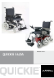
QUICKIE SALSA Directions for use
User Information Intended use power wheel chairs: Power wheelchairs are exclusively for a user who is unable to walk or has limited mobility, for their own personal use inand outdoor. When an Attendant Control Module is fitted, the Power Wheelchair may be operated by an assistant on behalf of the user. When a Dual Control Module is fitted the Power Wheelchair may be operated by the user, or control may be switched to an assistant to operate on behalf of the user.
Table of contents 1 2 Your Wheelchair 6 How to use this manual 6 2.1 Introduction..................................................................... 6 2.2 Guarantee....................................................................... 6 2.3 Warranty conditions......................................................... 6 3 Label explanations / Word definitions 7 3.1 Definitions of words used in this manual......................... 7 3.2 Label explanations...........................................
Armrest ENGLISH Controller Cushion Legrest Drive wheel Footplate Castor Backrest Skirt Guard Batteries Anti-tips 4 Quickie SALSA
Armrest ENGLISH Controller Cushion Legrest Drive wheel Footplate Front castor Backrest Skirt Guard Batteries Rear castor Quickie SALSA 5
1 Your Wheelchair We at Sunrise Medical want you to get the best out of your Salsa wheelchair. This Owner’s Manual will familiarise you with the chair and its features. It contains hints on everyday usage and general care in addition to information on the high quality standards which we adhere to and details about the guarantee. ENGLISH Your wheelchair should be delivered fully assembled for your use; there are a wide range of components and adjustments available on the Salsa.
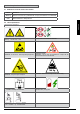
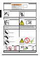
3 Label explanations / Word definitions 3.1 Definitions of words used in this manual Word Warning Note Advice to the user of a potential risk of injury if the advice is not followed General advice or best practice Label explanations ENGLISH 3.2 Definition Labels and their descriptions Warning - Do Not Touch - HOT WARNING – Do Not Touch - Static may damage equipment Lever position for the freewheel mechanism.
ENGLISH Labels and their descriptions Back Rest Recline Seat Lift Seat Tilt in Space The power Tilt and power Lift/Tilt modules are factory fitted for optimum stability and for conformance to strict standard requirements.
General safety warning and user tips 4.1 • • • • • • • • General warnings Always ensure that your wheelchair is switched off before attempting to mount or dismount. Always ensure that you are able to operate all controls from a comfortable position. Paying attention to your posture is essential to ensure your continued comfort and well being. Always make sure that you can be seen clearly, especially if you intend using your wheelchair in poor light.
4.10 Tyres Your wheelchair tyres can wear depending on use. Check them regularly in accordance with the service instructions in this manual, especially the pressure of the tyres. NEVER inflate the tyres using a garage forecourt airline, always use the pump provided. ENGLISH • • • 4.
Gradients: ascents When going uphill, keep the chair moving. Steer by moving the joystick from side to side. If you have stopped on a hill, you should start slowly. If necessary lean forward to prevent the tendency for the front wheels to lift. 4.21.2 Gradients: descents On descents, it is important not to let the wheelchair accelerate beyond its normal level of ground speed.
4.30 Using a kerb climber 4.30.1 Mounting a kerb or step (Fig 9) • All powered seating options need to be in home position. Your powered legrests may need to be adjusted to give enough clearance to mount or dismount the kerb. Always approach a kerb at 90° (Fig 7 & Fig 8) • Approach the kerb (step) head on driving forwards slowly and steadily and always at a 90° angle. Fig. 7 Fig.
joystick when you drive. Never drop the control system. When transporting your wheelchair, make sure that the control system is well protected. Avoid damage to cables. To improve the reliability of the control system keep exposure to extreme conditions to a minimum. Do not expose your control system or its components to damp for prolonged periods. If your control system becomes contaminated with food or drink clean it off as soon as possible. Fig. 13 4.31 Lap belt The lap belt kit. (Fig. 13).
5 Preparing your wheelchair for use 5.1 Handling the wheelchair ENGLISH Note: To dismantle the chair for transport or storage no tools are required. List of components when dismantled (components below are related to the maximum detachable parts and dependent on the type of seating system chosen): 1 pair of armrests 1 pair of legrests, 1 backrest (Std. Rehab/comfort seat only) 1 drive unit with seat frame 5.
DEUTSCH DO NOT switch on and operate the powerchair control system whilst the Emergency freewheel is disengaged. Always re-engage the drive mechanism on the rear wheels when the chair is not being pushed. To Disengage the Emergency freewheel pull out and push over the operating cam lever – see Fig A. Fig. 25c ENGLISH To Engage the Emergency freewheel pull out and push over the operating cam lever. The drive and brakes will NOT become operable until the internal parts are re-aligned.
5.7 Getting ready to drive • Operate the on/off switch. The battery gauge will blink then remain on after a second Check that the maximum speed is set to a level which suits you. Push the joystick to control the speed and direction of the wheelchair • • 5.8 Armrests 5.8.1 Armrests-removing and replacing (Fig. 28) The armrests on both sides of the wheelchair can be flipped up to allow side transfer. For side transfer flip the armrest all the way up until it goes into its mechanical stop.
Fig. 36 10. Use the 5mm fine height adjustment screw (C) to finish fine tuning the height. Turn counter-clockwise to increase height or clockwise to lower. Fig. 40 11. Tilt both armpads down (or up in the case of a lowered armrest) until the armpads are in the preferred angle. Check to see if the height is correct. (Refer to Number 10 for further height adjustment.) Fig. 41 Fig. 37 12. Retighten both armrest pivot bolts. (Use 20 N/m or 177 in/lb of torque.) 13.
3. Fig. 44 For larger adjustments, remove both sets of armpad adjustment bolts. ENGLISH Fig. 47 5.8.3 Armpad Position Adjustment (Fig. 45 - 48) 1. Fine armpad position adjustments (one to two inches) are possible by loosening the 4mm armpad adjustment bolts (E) and sliding the armpad forward or backward as required. Access to the rear adjustment bolt may require pivoting the armpad 4. Slide both armpads to the next set of attachment holes (refer to the chart).
do not injure your legs when legrests are extended. 5.9.4 WARNING - Always ensure that the legrests or footplates do not come into contact with the castors before driving the wheelchair. WARNING - Legrests are not to be used for lifting or carrying the wheelchair with an occupant. 5.9.1 1. Hanger depth adjustment (Fig. 53 - 55) Remove both sets of 5mm hanger depth adjustment bolts. Fig. 53 Fitting legrest 5.9.2 2. Slide both hanger receivers to the desired location.
5.9.5 ELR) Manual Articulating / Elevating Legrest (ALR/ To elevate: Pull the legrest upwards and stop at the desired height. The legrest will automatically lock in the chosen position. Fig. 57 ENGLISH To lower: Push the release lever slowly forward. The legrest will lower the angle. As soon as you release the lever, the legrest will be locked in the current position.
6.1 Seating 6.7 Firm seat board The firm seat board is designed to allow pressure relief cushions such as Jay to be used. 6.2 Seat cushions 6.3 Removable seat covers Seat width adjustment (Fig. 61 - 64) 1. Remove the 5mm width adjustment bolts (A) and the 4mm towel bar adjustment bolt (B) . Fig. 61 Seat cushions supplied by Sunrise Medical will have Velcro® strips that correspond to patches on the seat. You must ensure these are aligned prior to using the wheelchair.
6.8 Seat Depth Adjustment (Fig. 65 - 67) 1. Remove the 5mm depth adjustment bolts from both sides of the seat. 2. Tilt the backrest assembly forward or backward to the desired angle. See angle configurations below. Fig. 69 ENGLISH Fig. 65 2. Slide the rear backrest and armrests into the desired seat depth position. Reference seat depth position patterns (A) Fig. 66 3. Replace both sets of depth adjustment bolts. (Use 20 N/m or 177 in/lb of torque.) 3.
Fig. 72 3. Remove the top upholstery screws. The upholstery can now be moved and vertically compressed to provide access to the hidden Phillips-head bolts. 6. Move both backposts to the desired height. Fig. 76 7. Replace the backpost adjustment screws. (Use 10 N/m or 88.5 in/lb of torque.) Fig. 77 Fig. 73 8. If removed in Number 4, replace the towel bar and the towel bar bolts. (Use 10 N/m or 88.5 in/lb of torque.) 4. Remove the 4mm towel bar bolts and the towel bar.
10. Retighten the upholstery straps. 6.13 ENGLISH Fig. 80 Headrest To fit the headrest, fit the location bracket to the push handles, using the screws and nuts supplied, ensuring that they are fully tightened. The headrest height is changed by loosening the adjustment knob and sliding the inner vertical tube to the desired position and tightening the knob.
WARNING • It is possible to reverse the direction of an actuator relative to the direction of the joystick. Ensure you know which direction to move the joystick for the desired operation. Failure to do so may result in damage and/or injury. Please refer to Section 7 for details of your hand control Powered adjustable backrest: WARNING - Lowering the backrest by an angle of greater than 15° from vertical alters the balance of your wheelchair.
7.0 The VR2 Hand Control Series 7.1 VR2 On/off button: The on/off button applies power to the control system electronics, which in turn supply power to the wheelchairs motors. Do not use the on/off button to stop the wheelchair unless there is an emergency. (If you do you may shorten the life of the wheelchair drive components) ENGLISH Battery gauge: The battery gauge shows you that the wheelchair is switched on. It also indicates the status of the wheelchair. Refer to chapter 8.
There are common controls between the VR2 and the VR2-L control systems where a control differs it will be described below. All common controls can be found on the previous page. Lights and indicators: The SALSA can be equipped with lights and indicators. Where lights are not factory fitted, they may be fitted as an optional extra by an approved Sunrise Medical authorised dealer. WARNING Ensure that the lights and indicators are functioning correctly and lenses are clean before going outdoors at night.
Control Panel Joystick ENGLISH Charger & Programming Socket Battery Gauge Hazards Button On-Off Button Lights Button Max. Speed/Profile Horn Button Speed/ Profile Decrease Button Indication Actuator Button Speed/ Profile Increase Button Indicator Buttons VR2 Control Panel Layout Joystick Control Panel VR2-L Control Panel Layout Speed Indicator Max.
Always consult your Sunrise Medical authorised dealer when a diagnostic fault has appeared on your hand control. The battery gauge and maximum speed/profile indicator show the status of the control system. Battery Gauge is steady - This indicates that everything is OK. Battery Gauge flashes slowly - The control system is functioning correctly but the batteries need charging as soon as possible. Battery Gauge steps up - The wheelchair batteries are being charged.
9 Controller Mounts 9.1 General warnings ENGLISH Do not replace the joystick knob with any unauthorised item. It may cause hazardous operation and loss of control of the chair. It is important that the joystick boot is replaced if it is torn or brittle; failure to do so could cause substance damage to the controller and unexpected movement of the chair.
Fig. 94 Warning- Please read the owner’s manual supplied with the charger carefully. The general procedures and effects for the interference with the chair and the batteries remain valid. Warning- Do not expose any part of the battery to direct heat (i.e. naked flame, gas fire). Warning- When charging always place your charger on a hard surface in a room with good ventilation. Warning- You should not charge your batteries in outdoor conditions. 10.1 Batteries Salsa (Fig.
ENGLISH batteries. This has been agreed between Sunrise Medical and the battery manufacturers, to enable you to get the best out of your batteries. If a different care plan is followed, this may result in lower than expected performance from your mobility vehicle. 10.6 Maintenance free battery care plan 1. Only use an approved Sunrise Medical charger compatible with the vehicle to be charged. 2. Charge your batteries every night, regardless of the amount of use your mobility device has had during the day.
Do not disassemble charger; only have it repaired by the manufacturers. Incorrect re-assembly may result in a risk of electric shock or fire. To reduce the risk of an electric shock, unplug the charger from the outlet before attempting any maintenance or cleaning. Turning off the controls will not reduce the risk. Never place the charger directly above the battery being charged; gases from the battery will corrode and damage the charger.
Restraints should not be held away from body by wheelchair components such as armrests or wheels Incorrect placement of the head rest Fig. 108 Fig. 105 ENGLISH Pelvic restraints should make full contact across the front of the body near the junction of the thigh and pelvis Correct placement of the head rest Fig. 109 Fig. 106 Correct method 11.
SALSA tie down (Fig. 112 - 1117) Fig. 115 ENGLISH Fig. 112 DEUTSCH 11.6 Fig. 113 Fig. 116 Fig. 114 Fig.
12 Maintenance and Cleaning 12.4 ENGLISH It is important that you follow the following cleaning and maintenance schedule in order to keep your wheelchair in tip top condition. 12.1 Tyre maintenance and pressures If pneumatic tyres are fitted to your wheelchair it is important to regularly check the air pressure and for signs of wear. The correct pressures are between the minimum of 137 kiloPascals (20 psi, 1.37 bar) and the maximum 241 kiloPascals (35 psi, 2.
Use a cross screw driver to release the screw of the light or indicator glass. Take the glass off. This gives you access to the bulbs. • For the TUV lights 12V/3W bulbs with an E12 thread are required • For the TUV indicators 12V/5W bulbs with a 90° bayonet socket are required 12.12 Controller access To access the controller on the SALSA R(RWD) take the front shroud on the base between the front castor wheels off (Fig. 122/124).
Check the thin rubber gaiter or boot around the base of the joystick shaft for damage or splitting. Check visually only, do not handle the gaiter. Mounting: Make sure that all components of the control system are securely mounted. Do not over-tighten any securing screws. ENGLISH WARNING - Please refer to Service manual for any information about Torques. 12.
13 Specification sheets (EN 12184 & ISO 7176-15) Manufacturers (Europe): Sunrise Medical GmbH+Co.KG Kahlbachring 2-4 69254 Malsch/Heidelberg Deutschland Operating temperature: - 25°C to 50°C Storage temperature: -40°C to 65°C Moisture resistance: IPx4 No restrictions on humidity and air pressure ISO7176-15 Min. Max. Comments Overall length (with legrest) 1100 mm 1140 mm 70° hanger Overall width 580 mm 610 mm 12” / 14” wheels Total mass (w. batteries) 114.
ENGLISH Model: Quickie Salsa M (MWD) Maximum occupant mass (test dummy mass): 140 kg The wheelchair Quickie Salsa conforms to the following standards: a) requirements and test methods for static, impact and fatigue strengths (ISO 7176-8) b) power and control systems for electric wheelchairs — requirements and test methods (ISO 7176-14) c) climatic test in accordance with ISO 7176-9 d) requirements for resistance to ignition in accordance with ISO 7176-16 e) the product is specified as a Class B po
15 This section is designed to assist you in keeping a record of any service and repairs to your wheelchair. Should you decide to sell or exchange your vehicle in the future, this will prove most helpful to you. Your Service Agent will also benefit from a documented record and this manual should accompany the wheelchair when service or repair work is carried out. The Service Agent will complete this section and return the manual to you.
SALSA Battery Wiring Diagram ENGLISH 16 3 1 2 Charger Socket: Pin 1: Battery Positive Pin 2: Battery Negative Pin 3: Inhibit BATTERY CONNECTOR 80A RED -- + YELLOW BATTERY CONNECTOR 80A BLACK + 42 Quickie SALSA RED -- BLACK
Sunrise Medical GmbH & Co.KG 69254 Malsch/Heidelberg Kahlbachring 2-4 Germany 69254 Malsch/Heidelberg Tel.: +49 (0) 7253/980-460 Germany Fax: +49 (0) 7253/980-0 Tel.: 7253/980-220 www.sunrisemedical.com Fax: +49 (0) 7253/980-111 www.sunrisemedical.com Sunrise Medical Limited High Street Sunrise Medical Wollaston Limited West Street High Midlands Wollaston DY8 4PS England West Midlands DY8 4PS Tel.: +44 (0) 1384446688 England www.sunrisemedical.com Tel.: +44 (0) 1384446666 www.sunrisemedical.