Wheelchair Directions for use 000690678.
If you are visually impaired, this document can be viewed in PDF format at www.SunriseMedical.com or alternatively is available on request in large text.
Foreword Dear Customer, We are very happy that you have decided in favour of a high-quality product from SUNRISE MEDICAL. Use Wheelchairs are exclusively for a user who is unable to walk or has limited mobility, for their own personal use, when self-propelling and being moved by a third party (pushed by attendant) within the home and outdoors.
Table of Contents Foreword Use Area of Application. Definitions 1.0 General Safety Notes and Driving Limits 2.0 Warranty 3.0 Wheelchair components 4.0 Handling 5.0 Quick Release Wheels 6.0 Options Step Tubes Wheel locks Footplate Seating Castors Backrest Headrests Wheel alignment Frame adjustment Sideguard Push handles Crutch holder Anti tips Stabilising bar Transit wheels Lap strap Lap strap (continued) 7.
General safety notes and driving restrictions The engineering and construction of this wheelchair has been designed to provide maximum safety. International safety standards currently in force have either been fulfilled or exceeded in parts. Nevertheless, users may put themselves at risk by improperly using their wheelchairs. For your own safety, the following rules must be strictly observed. Unprofessional or erroneous changes or adjustments increase the risk of accident.
securely mounted parts (e.g. not on the footrests or the sideguards). Danger! When using the lifting ramp make sure that the anti-tip tubes fitted are positioned outside the danger area. Danger! Secure your wheelchair on uneven ground or when transferring (e.g. into a car) by using the wheel locks. Danger! For high amputees you must use anti-tip tubes. Danger! Before setting off, check that your tyre pressure is correct. For rear wheels it should be at least 3.5 bar ( 350 kPa). The max.
2.0 Warranty Warranty THIS DOES NOT AFFECT YOUR LEGAL RIGHTS IN ANY WAY. Warranty conditions 6) Consumable parts are normally excluded from the guarantee, except in the case that premature wear of the part is the direct result of a manufacturing fault. These parts include, amongst others, upholstery, tyres, inner tubes and similar parts. 1) Repair or replacement is carried out by the authorised 7) The above warranty conditions apply to all product Sunrise Medical dealer.
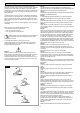
3.0 Wheelchair components 1. Push handles 2. Back sling 3. Sideguard 4. Seat sling 5. Footrest 6. Castors 7. Footplate 8. Fork 9. Quick-release axle 10. Wheel locks 11. Handrim 12. Rear wheel 13.
4.0 Handling Fig. 4.1 Folding up First remove the seat cushion from the wheelchair and flip up the (platform) footplate. Take hold of the sling or the seat tubes (Fig. 4.1) in the middle, from the back, and pull it upwards until the folding bracket (Fig. 4.2) clicks into place. Fig. 4.2 Transportation To move the mobility aid, the folded wheelchair should be lifted by holding the front part of the cross-brace and the push handles. Unfolding Push the release lever of the folding bracket (Fig. 4.
5.0 Quick Release Wheels Fig. 5.1 Quick-release axles on rear wheel The rear wheels are equipped with quick-release axles. The wheels can thus be installed or removed without using tools. To remove a wheel, simply depress the quickrelease button on the axle and pull the wheel off the axle. (Fig. 5.1). Quick release for quads/tetraplegics Please flip up the release lever (1). The take out the quick release axles and/or the wheels.
Wheel lock lever extension Fig. 6.4 The longer lever helps to minimize the effort needed to set the wheel locks. The wheel lock lever extension is screwed to the wheel locks. By raising this, it can be flipped forward (Fig. 6.4). CAUTION! Mounting the wheel lock too close toward the wheel will result in a higher effort to operate. This might cause the wheel lock extension lever to break! WARNING! Fig. 6.
Fig. 6.7 Footplate 2 Various footboards are available on the Xenon SA. These can be flipped up to make it easier to transfer to/from the chair. They are described individually. 1 Footrest and swing away latch When fitting the footrests these are fitted in the swungaway position (Fig. 6.7). Then simply turn them inwards until the interlock engages (1). To remove the footrests, use the lever (2) and swing the footrest outwards and lift off. Check that the footrest is correctly engaged. Fig. 6.
Width Adjustment of the footrests Fig. 6.13 If the footrest width needs to be adjusted, please undo the screw (1), set the desired width, by positioning 1, 2 or 3 spacers (2) from outer to the inner side and then refit the screws, (Fig. 6.13). Lightweight footrest The footrest angle can be adjusted by loosening the screws (2). Side protection panels can be fitted to the footrest using the mounting holes (3). These prevent the feet slipping off accidentally, (Fig. 6.14).
Seating Fig. 6.18 Seat sling Use the Velcro straps under the sling to tighten/loosen the seat sling. 1 Adjusting the seat height To change the seat height, please release the Allen screws (1) with an Allen key. Take the axle bracket (2) out of the axle stem (3) and remove or add the spacer (4). Then refit the axle bracket (2) into the axle stem (3) and re-tighten the screws (1), (Fig. 6.18 and 6.19). Tighten the 2 Allen screws to 7 Nm (Fig. 6.20). Fig. 6.
Rotate the axle bracket (Standard) Using the quick-release axles, take the wheels out of the axle plug / sleeve. Undo the screws (1) and remove the axle brackets (2) on both sides of the wheelchair. Rotate the axle bracket by 180° and refit it into the axle bracket (3) on the opposite side. Please note that the axle bracket has an asymmetrical shape. The adjustment offers changes in the centre of gravity in 2 cm steps. Always use the given torque (Fig. 6.22).
Castors Fig. 6.25 Setting the Castor, Castor adapter & Castor fork +8° If the wheelchair veers slightly to the right or left, or the castors flutter, it may be caused by one or more of the following: • Forward and/or reverse wheel motion has not been set properly. • The castor angle has not been adjusted properly. • Castor and/or rear wheel air pressure is incorrect; the wheels do not turn sufficiently freely. -8° Fig. 6.
Backrest Fig. 6.27 To adjust the back angle, please undo the Allen screw (1) and remove it. Set the desired position and then refit the screw in this position and tighten it to the given torque (Fig. 6.27). Folding backrest 1 To make it easier to transport the wheelchair, the top half of the backrest can folded down. To do this, press both levers (1) and fold the backrest down. When folding the backrest back up, please make sure that both sides are firmly interlocked (Fig. 6.28/6.29) Fig. 6.
Wheel alignment Fig. Fig.6.32 30 Adjusting the wheel alignment NOTE: To achieve the very best movement, the rear wheels must be adjusted to their optimum position. This means correctly adjusting the wheel alignment. To do this, measure [the distance between] both wheels front and rear to ensure that they are parallel to one another. The difference between both measurements should not exceed 5 mm. The parallel setting can be adjusted by loosening the screws (1) and rotating the axle adapter (2).
Sideguards Fig. 6.35 Single Post Height-Adjustable Armrests ATTENTION! Neither the sideguards nor the armrests are to be used for lifting or carrying the wheelchair. 2 3 1. Fitting a. Push the outer armrest rails down into the receiver which is mounted on the wheelchair frame. b. The armrest will automatically lock into place. 2. Height adjustment a. Turn the release lever for height adjustment (2) to the second stop point. b. Push the armpad up or down to reach the desired height. c.
Sideguards (continued) Fig. 6.39 2 1 Sideguard with clothes protector The clothes protector prevents clothes getting dirty from spray water, (Fig. 6.39). You can set the position in relation to the rear wheel by moving the sideguard. To do this, remove the screws (1 and 2). After setting to the desired position, re-tighten the screws (see the page on torque). WARNING! Neither the sideguards nor the armrests are to be used for lifting or carrying the wheelchair.
Crutch holder Fig. 6.44 Crutch holder (Fig. 6.44) This device permits crutches to be transported directly on the wheelchair. It has a Velcro loop to fasten crutches or other aids. 2 WARNING! Never try to use or even remove the crutches or other aids while moving. Anti tips Fig. 6.45 WARNING! Sunrise Medical recommends anti-tip tubes are fitted for all chairs. When fitting anti-tip tubes, use a torque of 7 Nm (2).
Stabilising bar Fig. 6.47 Folding stabilising bar This bar is used to stabilise the backrest. To be able to fold the wheelchair, the release lever must be pushed inwards (Fig. 6.47) or released and the stabilising must be flipped downwards. When unfolding the wheelchair, please make sure that the stabilising bar is locked into position. Transit wheels Fig. 6.48 Transit wheels Transit wheels should be used whenever your wheelchair would be too wide if the rear wheels were fitted (Fig. 6.48).
Lap strap Fig. 6.52 WARNINGS! • • • Before using the wheelchair make sure that the pelvic restraint belt is fitted. The pelvic restraint belt must be checked on a daily basis to ensure it is free from any obstruction or adverse wear. Always make sure that the lap strap is correctly secured and adjusted prior to use. DANGER! Fig. 6.53 If the strap is too loose, this could cause the user of the wheelchair to slip down and risk suffocation or serious injury.
Lap strap (continued) Fig. 6.57 When fastened check space between the lap belt and user. When correctly adjusted it should not be possible to insert more than the flat of the hand between the pelvic restraint belt and the user, (Fig. 6.57). The lap belt should be fxed so that the belt sits at an angle of 45 degrees across the users pelvis. The user should be upright and be as far back as possible in the seat when correctly adjusted.
7.0 Daily Checks 9.0 Maintenance and Care CAUTION! As the user, you are the first person to notice any possible defects. We therefore recommend that before each use, you check the items in the following list: • • • • Check for correct tyre pressures. Check that the brakes work correctly. Check that all removable parts are secure, e.g. armrest, footrest, quick-release axle etc. Check for visible damage e.g. on the frame, backrest, seat sling and back sling, wheels, footplate etc.
11.0 Disposal / Recycling of Materials 10.0 Trouble shooting Wheelchair pulls to one side • Check tyre pressure • Check to make sure wheel turns easily (bearings, axle) • Check the castor angle • Check to make sure both casters are making proper contact with the ground NOTE: If the wheelchair has been made available to you as part of a charity or medical loans scheme, then it may not belong to you.
13.0 Technical data 12.0 Nameplate Overall width: With standard wheels including hand rims, close mount: • in combination with aluminium sideguard: SW + 170 mm • in combination with plastic clothes protector: SW + 190 mm • With extra-narrow hand rim fitting, overall width is reduced by 20 mm.
Technical Specifications (continued) Maximum weight limit: Xenon SA up to a load of 125 kg Seat heights: The choice of frames, forks and castors as well as the size of the rear wheel (610 mm (24")), (635 mm (25")); determines what seat heights are possible. Table of Minimum and Maximum Values Parameter min. max. Parameter min. max.
Technical Specifications (continued) Castor Fork 98 x 32 111 x 32 111 x 45 76 mm (3") 123 x 45 138 x 45 174 x 45 Castor Fork 98 x 32 111 x 32 111 x 45 102 mm (4") 123 x 45 138 x 45 174 x 45 29 Seat height front / mm Seat height rear / mm 420 420 - 370 430 430 - 370 440 440 - 37 430 430 - 370 440 440 - 370 450 450 - 370 420 420 - 370 430 430 - 370 440 440 - 370 450 450 - 370 430 430 - 370 440 440 - 370 450 450 -370 460 460 - 370 440 440 - 370 460 460 - 370 4
Technical Specifications (continued) Castor Fork 98 x 32 111 x 32 111 x 45 127 mm (5") 123 x 45 138 x 45 174 x 45 Castor Fork 111 x 45 123 x 45 152 mm (6") 138 x 45 174 x 45 30 Seat height front / mm Seat height rear / mm 440 430 - 370 450 440 - 370 460 450 - 370 450 440 - 370 470 450 - 370 480 460 - 370 440 430 - 370 450 440 - 370 470 450 - 370 480 460 - 370 450 440 - 370 470 450 - 370 480 470 - 370 490 480 - 370 470 460 - 370 480 470 - 370 500 480 - 370 51
Technical Specifications (continued) Castor Fork 123 x 45 178 mm (7") 138 x 45 174 x 45 Castor Fork 76 mm (3") FROGLEG 102 mm (4") 127 mm (5") 152 mm (6") 178 mm (7") FROGLEG FROGLEG FROGLEG FROGLEG 31 Seat height front / mm Seat height rear / mm 480 480 - 370 490 490 - 370 500 500 - 380 510 510 - 390 490 490 - 370 510 510 - 390 520 520 - 400 530 530 - 410 520 520 - 400 530 530 - 410 540 540 - 420 560 560 - 440 570 570 - 450 Seat height front / mm Seat height
Technical Specifications (continued) Centre of Gravity Matrix Lightweight clamp Passive clamp Standard clamp 32
14.0 Torque Settings NOTE: If no specific torque information is given, the generic torque value for M6 screws is 7.
NOTES 34
NOTES Dealer signature and stamp 35
Sunrise Medical GmbH & Co.KG Kahlbachring 2-4 69254 Malsch/Heidelberg Germany Tel.: +49 (0) 7253/980-0 Fax: +49 (0) 7253/980-111 www.sunrisemedical.com Sunrise Medical Limited High Street Wollaston West Midlands DY8 4PS England Tel.: +44 (0) 1384446688 www.sunrisemedical.com Sunrise Medical S.L. Polígono Bakiola, 41 48498 Arrankudiaga – Vizcaya España Tel.: +34 (0) 902142434 Fax: +34 (0) 946481575 www.sunrisemedical.com Sunrise Medical S.A.