
User's Manual


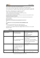


Table Of Contents

C/N:QL-19080102
Copyright © 2019 QUICKLINK. All rights reserved.
2. Interface Definition
The QL-1000 has a 8 PIN interface connector which contains the connections for power, I/O,
microphone, sos key, etc.
Figure 1. The 8 PIN connector on the QL-1000
Table 1. Description of the 8 PIN connections
Index
Description
Content
1
MIC POSITIVE
Single end, 2-2.2K microphone.
2
INPUT
Digital input, negative trigger
3
SOS INPUT
SOS Key input, negative trigger
4
POWER POSITIVE
External DC power input, 8-50V
5
OUTPUT 2
Open drain, 150mA max
6
ACC
Ignition input, positive trigger
7
OUTPUT 1
Open drain, 150mA max
8
GND
Power and digital ground
Table 2. Cable Color Definition
Definition
Color
Cables
Color
Definition
MIC +
Red
Blue
OUT 2
IN
Green
White
ACC
SOS IN
Red
Yellow
OUT 1
PWR
Red
Black
GND