
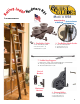
Installation Guide

5
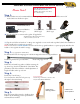
Tools Required For Assembly
4mm & 5mm allen wrenches.
#2 Phillips & #2 Square screw driver.
1/4” x 20 thread tap.
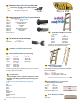
Step 1:
(A) Slide brackets into rail, recommended maximum spacing 32 inches apart. Pre-drill holes in wood if
needed and screw brackets in place.
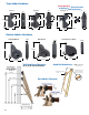
End View
General InstallatIon/specIfIcatIon GuIde
Please Note!!
Horizontal Bracket
(Roller type)
(C) Tap the end of the rail with a ¼” x 20 tap (not supplied) to screw in the end stop nial (done before installation
of rail). Install end stop with screw provided.
Note: Leave at least a 7 inch clearance above the rail for the top guide hardware to operate properly, and allow the
ladder to move against the wall for storage.
Rolled steel pin
(B) Use the splice kit to connect rails together. (If applicable)
Alignment Pin & Bar inserted into rail to
connect another section of rail
Aluminum Rail Rod
Vertical Bracket
(Roller type)
Vertical Bracket
(Hook type)
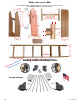
Step 2: (not applicable for CSH ladders)
Pre drill 23/64” holes for rung support rods below rung and screws for rung installation
Install rung with screws provided #8x2”, Install rung support rods
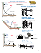
Step 3:
Drill holes and install top guides to ladder centering the
top dowel (top dowel recommended) of the ladder. e
placement of the holes will allow a small adjustment of
height of ladder, either up or down.
Top Turned Rung
16-1/4” long x 1-1/4”Dia., 7/8” Dia. ends.
14-3/8” Inside Width Unnished
Step 4:
Install Top Turned Rungs
Step 5:
Line up bottom rollers vertical to the oor when
ladder is in the climbing position pre-drill holes
and install bottom rollers.
Ladder in the
climbing position
Ladder in the
stored position
Use a forstner bit, drill 7/8” hole part way
through for the turned rungs