CHG-IOM-001 MAR-06
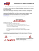
Installation and Maintenance Manual Report all Shipping Damage to Carrier IMMEDIATELY, Check units and box exterior for damage Note to Installer This manual to is to aid the qualified HVAC contractor in the Installation and Maintenance of this Quietside R410a Ductless Mini Split Please read and understand these instructions prior to installing the unit, failure to comply with these instructions may result in improper installation, operation and maintenance, possibly resulting in fire, electrical shock, pro
Installation and Maintenance Manual Installer Supplied Items Refrigerant Line Set : Flare Connection only, suitable for R410A with both lines insulated, max length 45ft Main System Breaker : Sized per unit requirements, to be mounted adjacent to Outdoor unit High Voltage Interconnect Wiring : 14 AWG wiring from Outdoor unit to Indoor unit for Power and Control Mounting Hardware : Wall Anchors, Condenser Pad etc Refrigerant : R410A required for additional line set charge Condensate Piping : Per local codes t
Installation and Maintenance Manual Controls and Components Units are supplied with a wireless remote controller, which communicates with the unit Microprocessor controller The return air temperature sensor mounted on the unit then controls the unit operation Several modes of operation are available to the end user depending on the type of comfort required All unit operating functions are controlled via the remote controller Unit operating modes are : Optional Controls and Components Low Ambient Controller
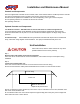
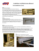
Installation and Maintenance Manual Unit Installation (Cont) Step3 Drill Hole for Line Set etc Remove mounting bracket from the rear of the Indoor unit, use a Phillips head screwdriver to remove the unit pipe strap, and if unit is a heat pump the defrost sensor also must be undone from its retainer. If mounting the unit on an outside wall measure from the edges of the unit to the center of the line set stub 90° bend to locate the the center of the wall penetration.
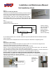
Installation and Maintenance Manual Unit Installation (Cont) Step 6 Install unit on Mounting Bracket Feed the line set stubs/condensate hose/wiring connections through the ø 3" hole, then locate the unit key slots onto the tabs on top of the mounting bracket. Bottom of the unit then latches onto the mounting bracket. Indoor unit is now installed, it should be plumb, level and flush with the wall.
Installation and Maintenance Manual Unit Installation (Cont) Step 9 Evacuation Gauges can now be attached to the service ports SERVICE PORTS HAVE A 5/16" CONNECTION TO GAUGES, WHICH IS DIFFERENT TO THE NORM Once the gauges are attached the line set can be leak checked using Nitrogen at 300 Psig Evacuate the unit down to a minimum of 200 Microns, break vacuum with Nitrogen to further leak check Re-evacuate the system down to 200 Microns or lower This is an R410A System it is essential that a deep vacuum be p
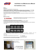
Installation and Maintenance Manual Unit Installation (Cont) Step 11 Controls Wiring Electrical Wiring should be done in accordance with all National Electrical Code (NEC) and local state/city building codes ALL CONTROLS WIRING BETWEEN INDOOR AND OUTDOOR UNIT IS HIGH VOLTAGE MINIMUM 14 AWG WIRE MUST BE USED Remove terminal covers from Indoor unit and wire to the terminals, small electrical screwdriver required Control wiring from the Outdoor Unit must be a point to point i.e.
Installation and Maintenance Manual Unit Start Up With the refrigerant system completely evacuated the system can now be opened to allow the refrigerant charge in the Outdoor unit to be released into the line set The Service Valves require a 6mm and a 5mm Allen wrench respectively to undo the valve stems Remove the BRASS caps from the Service Valves Open the SUCTION line Valve first to prevent any possible oil logging of the Capillary tube This can occur if the liquid line valve is opened first with the res
Installation and Maintenance Manual Wiring Diagrams