® ® Q T & PL T Series PLT essors Compressors 2 Stage Compr Instruction Manual This manual contains important safety information and must be carefully read in its entirety and understood prior to installation by all personnel who install, operate and/or maintain this product. Manual No.
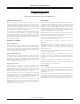
Warranty Statement Standard Warranty Quincy Compressor QT & PLT Series Reciprocating Compressors GENERAL PROVISIONS LIMITATIONS Quincy Compressor (The Seller) warrants to each retail purchaser (Purchaser) products of the Seller’s own manufacture against defects in material and workmanship. With respect to products not manufactured by the Seller, the Seller will, if practical, pass along the warranty of the original manufacturer.
Warranty Statement True Blue Warranty Quincy Compressor PRO, MAX & Xtreme Reciprocating Compressor Units WARRANTY PERIODS LIMITATIONS Quincy Compressor (Seller) warrants original basic compressors (see Standard Warranty for replacement basic compressors) on factory assembled PRO, MAX and Xtreme units for five (5) years from date of start-up, provided Purchaser registers the product with Quincy Compressor and maintains the unit with Quincy genuine parts and lubricant.
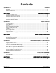
Contents SECTION 1 SAFETY Safety First ............................................................................................................................................. 1 Summary of Changes .............................................................................................................................. 3 SECTION 2 SYSTEM DYNAMICS Description & Application ......................................................................................................................
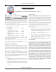
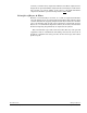
SECTION 1 SAFETY Safety First At Quincy Compressor safety is not only a primary concern, but a faithfully performed practice. Beginning with the design stage, safety is built into “The World’s Finest Compressor”. It is the intention of this manual to pass along the “safety first” concept to you by providing safety precautions throughout its pages. “DANGER !”, “WARNING !”, and “CAUTION !” are displayed in large bold capital letters in the left hand column to call attention to areas of vital concern.
•Do not operate the unit with any of its safety guards, shields, screens, enclosure panels or doors removed. •Do not remove or paint over any DANGER!, WARNING!, CAUTION!, or instructional materials attached to the compressor. Lack of information regarding hazardous conditions can cause property damage or personal injury. •Periodically check all pressure relief valves for proper operation.
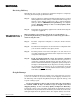
The owner, lessor or operator of any compressor unit manufactured by Quincy Compressor is hereby warned that failure to observe the safety precautions and procedures outlined in this manual may result in serious personal injury, damage to property, and may void your warranty. Quincy Compressor must authorize all warranty service. Before contacting your distributor or the factory, check the maintenance requirements and the troubleshooting guide for your compressor.
SECTION 2 SYSTEM DYNAMICS Description & Application Quincy Compressor QT Series and PLT Series compressors are heavy duty, air cooled, belt driven compressors. QT Series two stage compressors are splash lubricated and capable of delivering 175 PSIG of compressed air. The PLT Series compressors are pressure lubricated and capable of delivering 175 PSIG of compressed air.
enclosure, across the motor, compressor and intercooler. These compressors are designed to be operated with the compressor sheave turning in a counterclockwise rotation (as viewed “tummy to the sheave”). QT, PLT and Xtreme compressors should be operated in temperatures under 104°F. Principles of Dryers & Filters Moisture occurs naturally in air lines as a result of compression. Moisture vapor in ambient air is concentrated when pressurized and condenses when cooled in downstream air piping.
SECTION 3 INSTALLATION Receiving Delivery Immediately upon receipt of compressor equipment and prior to completely uncrating, the following steps should be taken: WARNING ! Step 1) Inspect compressor equipment for damage that may have occurred during shipment. If any damage is found, demand an inspection from the carrier. Ask the carrier how to file a claim for shipping damages. (Refer to SECTION 3, Freight Damage for complete details.) Shipping damage is not covered by Quincy Compressor warranty.
Retain all containers and packing for inspection by the carrier. A claim form can be requested from the carrier: Standard Form for Presentation of Loss and Damage Claims (form # 3208). Your claim will need to be substantiated with the following documents: a.) form #3208 b.) original bill of lading c.) original paid freight bill d.) original invoice or certified copy e.) other particulars obtainable in proof of loss or damage (photos, damage inspection, etc.
Excessive noise can be effectively reduced through various methods. Total enclosures, intake silencers, baffle walls, relocating or isolating the compressor can reduce noise levels. Care must be taken when constructing total enclosures or baffle walls. If not properly constructed or positioned, they could contribute to unacceptable noise levels or overheating. Consult your local Quincy distributor if assistance is required. WARNING ! Unusual noise or vibration indicates a problem.
QT & PLT Series 50161-106, January 2009 Quincy Compressor 9 3501 Wismann Lane, Quincy Ill. - 62305-3116 Fig. 3-1 3 Phase Magnetic Motor Starter With Automatic Start / Stop Control Wiring Schematic WP1744A (Rev. D) See Fig.s 3-5 & 3-6 for Xtreme (Cabinet Units) Wiring Schematics Overload Relay Contactor Connect incoming power lines at screw terminals L1, L2 & L3.
QT & PLT Series 50161-106, January 2009 Quincy Compressor 10 3501 Wismann Lane, Quincy Ill. - 62305-3116 Fig. 3-2 Single Phase Magnetic Motor Starter With Automatic Start / Stop Control Wiring Schematic WP1744B (Rev. D) See Pages 13 & 14 for Xtreme (Cabinet Units) Wiring Schematics Overload Relay Contactor Connect incoming power lines at screw terminals L1 & L2.
QT & PLT Series 50161-106, January 2009 Quincy Compressor 11 3501 Wismann Lane, Quincy Ill. - 62305-3116 Fig. 3-3 Single Phase 5 hp-230V Economy Units Automatic Start / Stop Control- Pressure Switch Wired to Motor Wiring Schematic WP1753 (Rev. H) See Fig.s 3-5 & 3-6 for Xtreme (Cabinet Units) Wiring Schematics Splice incoming power line connection to this white wire (wrapped in red tape). Install incoming power line connections at screw terminals L1 & L2.
QT & PLT Series 50161-106, January 2009 Quincy Compressor 12 3501 Wismann Lane, Quincy Ill. - 62305-3116 Fig. 3-4 Single Phase Combination Pressure Switch / Overload Relay Wired to Motor Connection Diagram See Fig.s 3-5 & 3-6 for Xtreme (Cabinet Units) Wiring Schematics Connect incoming power lines at screw terminals L1 & L2.
Connect incoming power lines at screw terminals L1, L2 & L3. Contactor Overload Relay Magnetic Starter Fig. 3-5 3 Phase Magnetic Motor Starter With Automatic Start / Stop Control Wiring Schematic WP1744A8 (Rev. A) For Xtreme Cabinet Units QT & PLT Series 50161-106, January 2009 Quincy Compressor 13 3501 Wismann Lane, Quincy Ill.
Connect incoming power lines at screw terminals L1 & L2. Contactor Overload Relay Magnetic Starter Fig. 3-6 Single Phase Magnetic Motor Starter With Automatic Start / Stop Control Wiring Schematic WP1744B7 (Rev. A) For Xtreme Cabinet Units QT & PLT Series 50161-106, January 2009 Quincy Compressor 14 3501 Wismann Lane, Quincy Ill.
Fig. 3-7 Start / Stop Control Piping Schematic WP1781B QT & PLT Series 50161-106, January 2009 Quincy Compressor 15 3501 Wismann Lane, Quincy Ill.
Fig. 3-8 Continuous Run - Load / Unload Control Piping Schematic WP1781C QT & PLT Series 50161-106, January 2009 Quincy Compressor 16 3501 Wismann Lane, Quincy Ill.
Fig. 3-9 Dual Control with Pilot Valve Unloading Piping Schematic WP1781A QT & PLT Series 50161-106, January 2009 Quincy Compressor 17 3501 Wismann Lane, Quincy Ill.
Mounting Proper mounting of QT & PLT series compressor units is crucial to the safe operation and longevity of the equipment. The installation requires a flat and level concrete floor or pad (for mobile units see Mounting FLANGE NUT Mobile Units). Satisfactory results can usually be obLeave loose & lock tained by mounting the compressor unit on vibration with a back-up nut RECEIVER FOOT isolating pads available from your local Quincy distributor.
WARNING ! Excessive compressor RPM’s (speed) could cause a pulley or sheave to shatter. In an instant, the pulley or sheave could separate into fragments capable of penetrating the belt guard and causing bodily harm or death. Do not operate the compressor above the recommended RPM (refer to SECTION 2, Specifications). Guards All mechanical action or motion is hazardous in varying degrees and needs to be guarded.
Induction System Air Intake A clean, cool and dry air supply is essential to the satisfactory operation of your Quincy QT or PLT Series air compressor. The standard air filter that the compressor is equipped with when leaving the factory is of sufficient size and design to meet normal conditions, when properly serviced, in accordance with the maintenance section of this manual.
where moisture can be easily removed. All service line outlets should be installed above the moisture traps to prevent moisture from entering the tool or device using the air. Manual shutoff valves, protected by pressure relief valves, should be installed at all service line outlets to eliminate leakage while the tools are not in use. Fig.
to Fig. 3-8, Typical Drop Leg & Component Location). WARNING ! Follow ASME code for air reciever tanks and other pressure containing vessels. Pressure vessels must not be modified, welded, repaired, reworked or subjected to operating conditions outside the nameplate ratings. Such actions will negate code status, affect insurance status and may cause property damage, severe injury or even death. A drain valve should be located in the bottom of the air receiver to allow for moisture drainage.
WARNING ! Oil and moisture residue must be drained from the air receiver daily or after each use. Accumulations of oil residue in the receiver can be ignited by embers of carbon created by the heat of compression, causing an explosion, damage to property and injury to personnel.
SECTION 4 START-UP & OPERATION Pre-starting Checklist WARNING ! Never assume a compressor is safe to work on just because it is not operating. It could restart at any time. Follow all safety precautions outlined in SECTION 5, Stopping For Maintenance. WARNING ! Failure to perform the pre-starting checklist may result in mechanical failure, property damage, serious injury or even death. Steps 1 through 12 should be performed prior to connecting the unit to a power source.
Step 12) (Xtreme Units)-Make sure all panels are securely mounted and fastened, the door is properly installed and latches are secured. Step 13) After all the above conditions have been satisfied, the unit can be connected to the proper power source. Xtreme Units (only) Step 14 Remove the front door. The rotation arrow on top of the motor must point towards the compressor. Jog the starter switch to check the rotation of the motor fan and pulley. The motor fan must blow cooling air towards the motor.
witnessed, stop the compressor and correct the problem. After two days of operation check belt tension, lubricant level, and inspect the system for leaks. A new or rebuilt reciprocating compressor should be run for a total of 100 hours at full discharge operating pressure to break-in the new piston rings. Until the rings are seated, the compressor will discharge higher than normal amounts of lubricant.
SECTION 5 MAINTENANCE & LUBRICATION Stopping for Maintenance The following procedures should be followed when stopping the compressor for maintenance or service: Step 1) WARNING ! Per OSHA regulation 1910.147: The Control of Hazardous Energy Source (Lockout/Tagout), disconnect and lockout the main power source. Display a sign in clear view at the main power switch stating that the compressor is being serviced. Never assume a compressor is safe to work on just because it is not operating.
densed liquids.) If lubricant is contaminated, drain and replace. •Drain receiver tank, drop legs and traps in air distribution system. Receiver tanks subjected to freezing temperatures may contain ice. Store the compressor unit in a heated area before attempting to drain moisture from the tank. •Give compressor an overall visual inspection and be sure safety guards are in place. •Check for any unusual noise or vibration. •Check for lubricant leaks.
Lubrication QT and PLT Series basic compressors and units are normally shipped from the factory with break-in lubricant in the crankcase. Before starting your compressor, check the lubricant level in the crankcase. The lubricant level of QT-5, PLT-5, QT-7.5, PLT-7.5, QT-10 and PLT-10 compressors must be kept at the top of the sightglass. The lubricant level of QT-15, PLT-15, QT-30 & QT-54 compressors must register between the high and low marks on the dipstick.
Pulley / Sheave Alignment & Belt Tension Improper pulley/sheave alignment and belt tension are causes for motor overloading, excessive vibration, and premature belt and/or bearing failure. To prevent this from happening, check the pulley/sheave alignment and belt tension on a regular basis (refer to SECTION 5, Maintenance Schedule). Periodically inspect the motor pulley(s) and compressor sheave(s) for oil, grease, nicks or burrs. Clean or replace if necessary. Make sure they are securely fastened.
Step 2) Determine the amount of deflection ( in inches) required to measure deflection force (in pounds) by multiplying the span length x 1/64 (.016) (i.e. 32” span length x 1/64 [.016] = 1/2”[.50] of deflection required to measure deflection force). POCKET CLIP Step 3) Lay a straightedge across the top outer surface of a drive belt from pulley to sheave.
WARNING ! Never exceed the designed pressure for the system or overload the motor beyond its Maximum Amp Draw. * Full Load Amps x Service Factor = Maximum Amp Draw WARNING ! Never assume a compressor is safe to work on just because it is not operating. It may be in the automatic stand-by mode and may restart any time. Follow all safety precautions outlined in SECTION 5, Stopping For Maintenance.
PILOT VALVE ADJUSTMENTS All adjustments made to the pilot valve must be performed by a qualified technician. The adjustments must be made while the unit is operating, therefore, extreme caution must be taken while working on the unit. Observe all necessary precautions. Always use a back-up wrench and make all differential and unload pressure adjustments in very small increments (1/8 turn). WARNING ! The pressure switch and / or pilot valve are set at the factory for maximum efficiency.
SECTION 6 Trouble TROUBLESHOOTING Probable Cause Low discharge pressure •Restricted inlet •Defective compressor valves or valve unloading mechanism •Leaks in the compressed air distribution system at fittings, connections, etc.
Trouble Probable Cause Excessive drive belt wear •Pulley/sheave out of alignment •Belt too loose or too tight •Belt slipping •Pulley/sheave wobbling •Pulley/sheave groove damaged or rough •Incorrect belts Low oil pressure •Oil sump strainer plugged •Excessive leakage at crankshaft seals •Low oil level •Oil pump incorrectly assembled to the bearing carrier (“o”ring not properly located between oil pump body & bearing carrier) •Oil pressure adjusting screw not set properly •Defective oil pressure gauge
Trouble Probable Cause Intercooler pressure abnormally low (Two stage models only) •Compressor valves or head unloaders in first stage not functioning properly or defective •Restricted air inlet filter or suction line •Pilot valve or pressure switch set incorrectly or defective •Pressurized air at head unloader not venting properly when demand for air is required •Compressor valve or head gasket leaking •Worn piston rings •Defective pressure gauge •Leaking air at intercooler or intercooler connections C
Trouble Probable Cause Excessive oil consumption •Compressor runs unloaded too long •Worn piston rings •Restricted intake system •Compressor running too hot •Breather valve not functioning properly •Oil level in crankcase too high •Oil viscosity wrong for the application •Connecting rod out of alignment, bent or twisted •Leaking oil seal •Piston rings not seated (allow 100 hours for seating) •Wrong oil (may be a detergent oil with a tendency to foam) •Inferior grade of oil Excessive current draw (To dete
SECTION 7 REFERENCE INFORMATION Decal Locations Typical QT & PLT Series Unit with Horizontal Receiver Typical QT & PLT Series Engine Driven Unit with Horizontal Receiver QT & PLT Series 50161-106, January 2009 Quincy Compressor 38 3501 Wismann Lane, Quincy Ill.
Typical QT & PLT Series Unit with Vertical Receiver QT & PLT Series 50161-106, January 2009 Quincy Compressor 39 3501 Wismann Lane, Quincy Ill.
Typical Xtreme Base Mounted Unit Typical Xtreme Tank Mounted Unit QT & PLT Series 50161-106, January 2009 Quincy Compressor 40 3501 Wismann Lane, Quincy Ill.
responsible for loss or damage in transit after having received “In Good Order” receipt from the carrier. All claims for loss or damage in transit should be made to the carrier. TITLE & LIEN RIGHTS: The equipment shall remain personal property, regardless of how affixed to any realty or structure. Until the price (including any notes given therefore) of the equipment has been fully paid in cash, Seller shall, in the event of Buyer’s default, have the right to repossess such equipment.
MAINTENANCE SCHEDULE CHECKLIST Use this form to develop a routine maintenance schedule and record of performed maintenance. In the numbered columns enter the initials of the person who performed the maintenance and the date. Enter additional maintenance procedures in the spaces provided in the left hand column as needed per your application. Equipment operating under humid or dirty conditions may require shorter intervals between scheduled maintenance.
Recipr ocating / Systems: Reciprocating 217.222.7700 Air Master 217.277.0270 E-mail: Website: info@quincycompressor.com quincycompressor.com quincyairmaster.com © 2006 Quincy Compressor, an EnPro Industries company All Rights Reserved. Litho in U.S.A.