
Installation Guide

QT & PLT Series Quincy Compressor
50161-106, January 2009 25 3501 Wismann Lane, Quincy Ill. - 62305-3116
Step 12) (Xtreme Units)-Make sure all panels are securely mounted and
fastened, the door is properly installed and latches are secured.
Step 13) After all the above conditions have been satisfied, the unit can be
connected to the proper power source.
Xtreme Units (only)
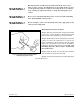
Step 14 Remove the front door. The rotation arrow on top of the motor must
point towards the compressor. Jog the starter switch to check the
rotation of the motor fan and pulley. The motor fan must blow
cooling air towards the motor.
Step 15 Reinstall the front door and secure the latches.
QT & PLT Compressor Units (only)
Step 14) Jog the starter switch to check the rotational direction of the
compressor. It should agree with the rotation arrow embossed on
the compressor sheave.
Step 15) Check for proper rotation of the cylinder cooling fan (fins inside
sheave). The fan should blow cooling air across the cylinder.
Initial Starting & Operating
This instruction manual, as well as any instructions supplied by manufactur-
ers of supporting equipment, should be read and understood prior to starting
the compressor. If there are any questions regarding any part of the instruc-
tions, please call your local Quincy distributor, or the Quincy Compressor
factory.
With the pre-starting checklist completed and satisfied, start the compres-
sor. Watch and listen for excessive vibration and strange noises. If either exist,
stop the compressor. Refer to SECTION 6, Troubleshooting for help in
determining the cause of such problems.
If you are starting a pressure lubricated model, check the oil pressure.
Compressors producing up to 175 PSIG of discharge air pressure should
maintain 18 to 20 PSIG of oil pressure.
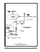
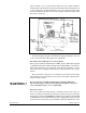
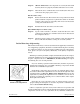
Normally the oil pressure does not need to be adjusted. But if it does,
loosen the locknut on the adjustment screw located on the right side of the
oil pump housing (see Fig. 4-1, Oil Pressure Adjustment). Increase the
oil pressure by turning the adjustment screw clockwise; decrease the oil
pressure by turning the adjusting screw counterclockwise. After adjust-
ment tighten the locknut.
Check the air receiver pressure gauge or system pressure gauge for
proper readings. If inadequate or excessive air pressure conditions exist,
refer to Section 6 Troubleshooting.
Observe compressor operation closely for the first hour of operation and
then frequently for the next seven hours. After the first eight hours, monitor the
compressor at least once every eight hours. If any abnormal conditions are
Pix 1220
Fig. 4-1
Oil Pressure Adjustment
OIL
PRESSURE
ADJUSTMENT
SCREW