
Product Manual


Single Stage Series Quincy Compressor
1312101105, September 2013 4 3501 Wismann Lane, Quincy IL - 62305-3116
the feet are not stressed in any manner. Leave the
locknut loose! Uneven feet drawn tightly to the
concrete pad will cause severe vibrations resulting
in cracked welds or fatigue failure. The customer is
responsible for pro viding a suitable foundation &
isolator mounting where necessary.
The compressed air supply line from the tank of
a stationary unit must be equipped with a pressure
and temperature rated flexible connection.
SYSTEM COMPONENTS
Drive Pulleys / Flywheels
Drive pulleys and compressor flywheels must be prop-
erly aligned and tensioned to specifications. (Refer
to Belt Alignment & Adjustment.)
WARNING !
Excessive compressor RPM’s could cause a pulley
or ywheel to shatter, possi bly causing bodily harm
or death. Do not operate the compressor above
the rec om mended RPM. (Refer to DESCRIPTION &
APPLICA TION.)
Guards
Guardsmustbedesignedandmountedincompliance
with OSHA safety and health standards 29 CFR
1910.219inOSHAmanual2206,andanystateor
local codes. They must provide protection from mov-
ing parts while still al lowing full air flow for cooling
purposes.
WARNING !
Guards must be fastened in place before starting
the com pressor. Always disconnect and lockout
the power supply to the unit before removing the
guard.
Check Valves
Check valves are designed to allow air to flow freely in
one direction only. A properly sized check valve must
be provided. Do not rely on a check valve to isolate
a com pressor from a pressur ized tank or com pressed
air delivery system dur ing maintenance proce dures.
Pressure Regulator
This type of valve allows the operator to control the
air pressure setting of the compressor discharge. A
gauge is provided to indi cate the air pressure.
Pressure Relief Valves
Pressurereliefvalvesaidinpreventingsystemfail-
ures by relieving system pressure when com pressed
air reaches a predetermined pressure level. All air
receivers must be equipped with an adequately sized
pressure relief valve. This type of valve is preset by the
manufacturer and must not be modi fied in any way.
Pressurereliefvalvesaretobeplacedaheadof
any po tential blockage point which includes, but not
limited to, shutoff valves, heat exchangers, pulsa-
tion dampeners, and discharge silencers. Ideally the
pressure relief valve should be threaded directly into
the pressure point it is sensing, not connected with
tubing or pipe, and always pointed away from any
chance bystander.
WARNING !
Pressure relief valves must be pro vided to protect
com pressed air systems in ac cordance with ASME
B19 safety standards. Failure to provide properly
sized pres sure relief valves may cause property
damage, severe per sonal injury or even death.
WARNING!
Do not use plastic pipe (PVC) anywhere in a com-
pressed air system. Serious injury or death could
result.
Compressor Controls
Start/Stop
Electricmotorpoweredunitsareequippedwitha
pressure switch as standard equipment for start/
stop operation. The pressure switch (when set to the
“AUTO”position)reactstothedemandforcompressed
air and allows the motor to start. When the de mand is
satised,theunitstops.Pressureswitchesprovided
by Quincy Compressor are preset at the factory and
should only be modified by a qualified technician.
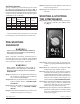
PressureswitchesequippedwithanOFF/AUTOknob
(see Fig. 5)shouldbesettothe“OFF”positionwhen
connecting or disconnecting the power cord from the
electrical outlet or when changing air tools.
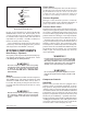
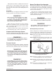
HORIZONTAL TANK UNITS
ANCHORED
VERTICAL TANK UNITS
ANCHORED
HORIZONTAL TANK UNITS
UNANCHORED
1/2” locknut
1/2” at washer
tank foot
isolator backing plate
1/2” x 2” bolt
isolator
1/2” locknut
1/2” at washer
tank foot
isolator backing plate
isolator
1/2” oor stud
(provided by customer)
1/2” oor stud
(provided by customer
)
tank foot
1/2” locknut
1/2” at washer
Fig. 2
Anchoring Vertical Tank Units