
Product Manual


Single Stage Series Quincy Compressor
1312101105, September 2013 5 3501 Wismann Lane, Quincy IL - 62305-3116
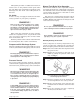
This system provides a loadless start feature. A
release valve on the pressure switch opens when
the unit shuts down and bleeds off pressure in the
discharge line. The check valve holds pressure in
the tank.
Air Intake
A clean, cool, dry, air supply is essential to the satis-
factory operation of your Quincy compressor.
WARNING !
Never locate the compressor where toxic, volatile
or cor rosive vapors, air tempera tures exceeding
104°F, wa ter, or extremely dirty air could be ingested.
The compressor could be damaged by these atmo-
spheres and result in in jury or death.
When using the compressor for spray painting,
isolate the compressor as far away from the work
area as practical, employing extra air hose rather
than an extension cord.
Warranty will be void if a failure is determined to
be caused by dust, dirt or other contaminants.
Compressed Air Discharge System
All parts of the discharge piping should fit so as not to
create any stress between the piping and connections.
WARNING !
Discharge piping can exceed 350°F when compres-
sor is operating. Do not use plastic pipe or lead tin
soldered joints for a discharge line.
Pressure Vessels
Air receiver tanks and other pressure contain ing
vessels must be equipped with a properly sized pres-
sure re lief valve, pressure gauge, and a tank drain.
WARNING!
Oil and moisture residue must be drained from the
air receiver daily or after each use. Accumulations
of oil residue in the receiver can be ignited by em-
bers of carbon created by the heat of compression,
causing an explosion, damage to property and injury
to personnel.
WARNING !
Follow ASME code for air receiver tanks and other
pressure containing vessels. Pressure vessels must
not be mod ied, welded on, or re paired. Such ac-
tions may cause property dam age, se vere injury,
or even death. Always replace worn, cracked or
damaged tanks.
Manual Tank Drain Valve Operation
The manual tank drain valve on portable compres-
sors and some stationary compressors is located on
theundersideoftheairtank.Portablecompressors
can be tilted in the direction of the drain to allow
removal of tank moisture.
Safe removal of tank moisture from the tank is
dependent upon an internal tank pressure of 20 to
30PSIG.Highertankpressuresaredangerousand
couldcauseseriousinjury!
WARNING!
Do not open a manual tank drain valve on any air
tank containing more than 30 PSIG of air pressure!
WARNING!
Never attempt to relieve an air tank by removing a
pipe plug or any other system component!
Manually Draining An Air Tank:
Tank(s) subjected to freezing temperatures may
contain ice. Store the compressor in a heated area
before attempting to drain moisture from the tank(s).
Step 1) Disconnect and lockout the compressor from
the power source.
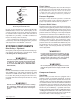
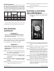
Step 2) Reduce the air pressure in the tank to 30
PSIG by pulling the pressure relief valve
ring (see Fig. 3).
Fig. 3 Checking Pressure Relief Valves
& Relieving System Pressure
Step 3)Positionyourselfsothatthemoistureand
air to be expelled can not cause you harm.
Step 4) Slowly open the drain valve and allow the
moisture and air mixture to drain from the
tank.
Step 5)Once the moisture has been completely
drained, close the drain valve.