
Product Manual


Single Stage Series Quincy Compressor
1312101105, September 2013 6 3501 Wismann Lane, Quincy IL - 62305-3116
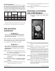
Air Tank Inspection
Quincy Compressor recommends that all air tanks
be inspected at scheduled intervals. Refer to Fig. 4
Recommended Air Tank Inspection Intervals for
relative information. Measure tank wall thickness at
several locations, including the lowest point where
condensation can accumulate.
Tank
Capacity
Horizontal
or
Vertical
Minimum Allowable
Wall Thickness
Visually
Inspect
Hydrostatically
Inspect
Head Shell
20 Gal. Horizontal .094 .094 Yearly 10 Years
36 Gal. Vertical .094 .094 Yearly 10 Years
60 Gal. Vertical .094 .094 Yearly 10 Years
Fig. 4 Recommended Air Tank Inspection Intervals
Refer to federal, state or provincial, or local codes
for mandatory air tank maintenance information.
PRE-STARTING
CHECK LIST
WARNING !
Failure to perform the PRE-STARTING CHECKLIST
may result in mechanical failure, prop erty damage,
se ri ous injury or even death.
Steps 1 through 6 should be performed prior to
operating the unit. If any condition of the checklist
is not satisfied, make the necessary adjustments or
corrections before starting the compressor.
WARNING !
Never assume a compressor is safe to work on
just be cause it is not operating. It could restart at
any time. Fol low all safety precau tions outlined in
MAINTENANCE.
Step 1) Compressors are shipped with lubricant in
the crankcase. Check for proper lubricant
level. (Refer to Lubrication.)
Step 2) Make sure all pressure relief valves are cor-
rectly installed. (Refer to SYSTEM COM-
PONENTS.)
Step 3) Be sure all guards are in place and securely
mounted. (Refer to SYSTEM COMPO-
NENTS.)
Step 4) Check all hoses and fittings for weak or worn
conditions and replace if necessary.
Step 5) Check fuses, circuit breakers, and overload
relays for proper sizes.
Step 6)Openthetankdrainvalveinthebottomof
the tank.
STARTING & STOPPING
THE COMPRESSOR
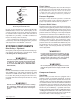
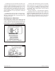
Step 1)MakesuretheOFF/AUTOknobonthepres-
sureswitchisturnedtothe“OFF”position
(see Fig. 5).
Fig. 5 Pressure Switch
Step 2) Turn on the power supply or plug the power
cord into a properly grounded and rated power
source.
Step 3)StartthecompressorbyturningtheOFF/
AUTOknobtothe“AUTO”position.
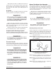
Step 4) At initial start-up, verify that the compres-
sor flywheel is rotating counterclockwise (as
viewed from the flywheel side of compressor).
Watch and listen for excessive vibration and
unusual noise. If either exist, stop the com-
pressor and refer to TROUBLESHOOTING.
Step 5)Newcompressorsshouldberunwiththetank
drain valve open for 1 hour to break-in the
compressor. This will allow the compressor
time to warm up and seat the rings.
Step 6)T o stopthecompressor,turntheOFF/AUTO
knobtothe“OFF”position.Carefullyunplug
the power cord from the power source or turn
off the power supply.