
Service manual
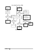
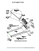
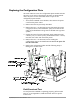

Replacing the Configuration Plate
On North American units, the configuration plate module includes
the power cord, which is attached to the plate. On international
units, the power cord is removable and is not part of the
configuration plate module.
1. Turn off the treadmill circuit breaker, then remove the power
cord from the power outlet.
2. Remove the hood as previously described.
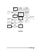
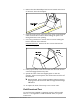
3. Remove the two ¼-20 hex head screws that attach the power
cord ground wires to the headframe. (They are located in the
center of the headframe. The ground is marked with a ground
symbol.)
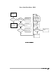
4. Unplug the wires from the VSD board (North American units:
3 wires (115v) or 2 wires (230v)), International units: 2 wires).
Note the wire colors and connection points.
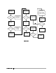
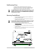
5. Remove the two ¼-20 hex-head screws holding the
configuration plate to the headframe. Do not let the plate fall
into the VSD PCBA.
6. Replace the configuration plate module following Steps 2
through 5 in reverse order.
Field Functional Test
To verify that the treadmill is operating properly, perform Field
Test No. 2. See Appendix D, Field Functional Tests for specific
instructions.
¼ ½
Repair/Replacement and Calibration 4-6