
Installation Guide

Package Contents
Warnings and Cautions
1of2
Assembly Instruction Sheet #IS-AI1720IB
For Style AI1720IB
Thank you for purchasing a Quoizel product.
Need assistance with parts or assembly? Call Quoizel customer service at 1-631-273-2700
or visit us on-line at www.quoizel.com
2015 QuoizelInc.
Turn off electricity at circuit breaker or main fuse box before installation. Consult a licensed electrician if in doubt.
These instructions are provided for your safety. It is very important you read them completely before installing the fixture. We strongly
recommend that a licensed, professional electrician perform the installation.
Disconnect fixture from power source before replacing bulbs. Make sure bulbs are given sufficient time to cool before removal. Do not subject
glass parts to any shock while in operation or shattering may result.
A
Crossbar
Assembly
x1
C
Shade
x1
B
Fixture
Body
x1
July2015
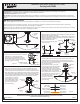
STEP 1 Install Crossbar Assembly-
A. Pass the supply wires through the Crossbar
Assembly (A). Attach the Crossbar
Assembly (A) to the Outlet Box with the
head of the Green Ground Screw facing
you. Secure it with Outlet Box Screws (not
included). Tighten until snug.
Supply Wires
with Ground Wire
Outlet Box Screws
(not included)
Outlet
Box
Figure 1
STEP 2 Fit Ceiling Canopy to Crossbar Assembly-
A.
eiling canopy on Fixture Body (B) to the
eiling canopy
ceiling
Remove mounting balls from the Crossbar Assembly (A). Fit the
c Crossbar Assembly (A)
and secure with mounting balls. Note: The c
should be snug against the and the mounting balls.
If
on Fixture
Body (B)
not, adjust the length of the nipple on the Crossbar Assembly (A)
by unscrewing the preassembled hex nut and lock washer and then
screwing the mounting screws in or out of the crossbar until the
Mounting
Screw
Hex Nut and
Lock Washer
B
Mounting
Ball
Figure 2
A
correct length is achieved.
Once the ceiling canopy on
Fixture Body (B) is secure,
remove the mounting ball
and ceiling canopy and
proceed to Step 3.
A
Pleasegoto forproduct cleaningtips. Goto the selection.
(4)A19MediumBase 100WMaximum.AlternateBulbs (4)23W CFL.
30-45minutes
Identifyand inspectall partsbefore beginninginstallation. Checkpackage contentlist anddiagrams belowto besure allparts are
present.If anyparts aremissing ordamaged, donot attemptto assemble,install, oroperate thefixture. Contactcustomer servicefor replacement
parts.
www.quoizel.com Care+ Maintenance
LightSource:
EstimatedAssemblyTime:
Preparation:
ToolsRequired: Flatheadscrewdriver, Phillipsscrewdriver, pliers,wire cutters,wire strippers,electrical tape,safety glasses.
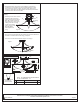
STEP 4 - Attach Lanyard
A. The purpose of the lanyard is to provide the installer a means to
support the fixture from the junction box while connecting the
electrical wires. This enables the fixture to hang from the junction
Crossbar
Button Stop
Lanyard
Slot
box and your hands are free to make
the wire connections.
B.TurntheButtonStopsoitmaybe
inserted into the Crossbar slot. Make
sure the Button Stop is completely
inside the Crossbar. Slowly release
the fixture to make sure it is supported
by the Button Stop. Proceed to the
wiring steps in the next step. Once you
are complete with the wiring there is
nothing to do with Lanyard. The
Lanyard will push into
the junction box when
the fixture is placed for
final mounting.
Figure 4
STEP 3 - Install Shade
A. Refer to Side Arm Orientation) Unfold Side Arms of the Side Arms
Assembly (E) to proper locations.
B. Remove Lock Balls from the Shade (C). Place Tabs at the ends of
Side Arms through the Bolt in the Shade (C) and secure with Lock
Bolt
Tab
Side Arm Orientation
Lock Ball
Figure 3
A
A View
C
Hex Nut
Side Arm
Balls. Hand tighten until sung.
C. Tighten the Hex Nut in the
Ceiling Canopy to secure Side
Arms until snug.
STEP 5 - Wire Connections
White wire
from supply
White wire
from fixture
Black wire from
supply (or Red)
Black wire
from fixture
Ground wire
from supply
Ground wire
from fixture
Figure 5