
Installation Guide

1of2
6 CORPORATE PARKWAY
GOOSE CREEK SC 29445
www quoizel com
,.
..
Thank you for purchasing a Quoizel product.
Need assistance with parts or assembly? Call Quoizel customer service at 1-631-273-2700
or visit us on-line at www.quoizel.com
2015 QuoizelInc.
Package Contents
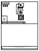
STEP 2 Drill Pilot Holes on Post-
A. Carefully fit the Post Fitter over the
end of the Post (not supplied),
making sure the Post Fitter is fully
seated.
B. Mark the drill point for the (3)
Mounting Screws, using (3)
Mounting Holes as reference. After
marking hole locations, remove
fixture from post and drill 1/16” pilot
holes for screws.
Post
Post Fitter
Figure 2
Pleasegoto forproduct cleaningtips. Goto the selection.
(1)A21MediumBase bulb150W Maximum,Alternatebulb(1) 42WCFL.
www.quoizel.com Care+ Maintenance
LightSource:
ToolsRequired:Flathead screwdriver,Phillips screwdriver,pliers, wirecutters, wirestrippers, electricaltape, safetyglasses.
EstimatedAssemblyTime:
Preparation:
20-30minutes
Identifyand inspectall partsbefore beginninginstallation. Checkpackage contentlist anddiagrams belowto besure allparts are
present.If anyparts aremissing ordamaged, donot attemptto assemble,install, oroperate thefixture. Contactcustomer servicefor replacement
parts.
Warnings and Cautions
Turn off electricity at circuit breaker or main fuse box before installation. Consult a licensed electrician if in doubt.
These instructions are provided for your safety. It is very important you read them completely before installing the fixture. We strongly
recommend that a licensed, professional electrician perform the installation.
Disconnect fixture from power source before replacing bulbs. Make sure bulbs are given sufficient time to cool before removal. Do not subject
glass parts to any shock while in operation or shattering may result.
White wire
from supply
White wire
from fixture
Black wire from
supply (or Red)
Black wire
from fixture
Ground wire
from supply
Ground wire
from fixture
Figure 3
STEP 4 Attach Fixture Body to Post-
A. Coat the top 1” of the Post with Clear
Silicone Caulk (not supplied) and
position the Post Fitter onto the Post. Be
sure to seat it completely, aligning the
holes in the Fitter with the 1/16” Pilot
Holes drilled into the Post.
B. Secure the Fixture to Post with (3)
Mounting Screws (A).
Your fixture is now assembled and
ready to use. Enjoy!
A
Mounting Screw
x3
D
Fixture
Body
x1
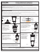
STEP 1 Install Bulb and
Fixture Hood
-
A. This fixture uses standard
bulb with standard screw
base. Maximum 150 watts.
Insert bulb and screw snugly
into place.
B. Place the Fixture Hood (C)
onto the top edge of the
Fixture Body (D) and secure
with Lock Screws (B). Hand
tighten until snug.
Bulb
Socket
Figure 1
Assembly Instruction Sheet #IS-BFD9010
For Styles BFD9010PN and BFD9010K
Mounting Hole
STEP 3 - Wire Connections
A. Use standard wire connectors (not included) to make all wire
connections. (Connectors are not included with fixture.) Twist
connectors until wires are tightly joined together. Wrap each
connection with approved electrical tape and carefully stuff all the
connected wires into the Outlet Box.
Post
Post Fitter
Figure 4
Mounting Hole
A
B
Lock
Screw
x2
C
Fixture
Hood
x1
C
B
D
STEP 5 - Replace Glass Panel
A
B Unscrew Cup Head Screws in
the Cage with Glass Panel.
Remove and
from the Cage.
. Remove F xture Hood from
F xture by unlocking Flat
Head Screws.
.
C. Reverse above steps to
reinstall the replacement
Glass Panel onto fixture.
i
i
Ring Glass
Panels
Figure 5
March2015
Fxture
Hood
i
Flat Head
Screw
Cup Head
Screw
Ring
Glass
Panel
Cage