
Installation Guide


Hardware Contents
Package Contents
Quoizel, Inc.
6 Corporate Parkway
Goose Creek, SC 29445
Customer Service
Phone 631.273.2700
Fax 631.231.7102
www.quoizel.com
ToolsRequired:Flathead screwdriver,Phillips screwdriver,pliers, wirecutters, wirestrippers, electricaltape,
safetyglasses.
BulbRecommended:
EstimatedAssemblyTime:
Preparation:
Fixturecan onlybe mountedin thedirection indicatedon page2.
(2)Medium BaseDecorative Filament60W bulbs(provided), Maximum100W,Alternate
bulb(2) 23WCFLMaximum.
30-45minutes
Identifyand inspectall partsbefore beginninginstallation. Checkpackage contentlist anddiagrams
belowto besure allparts arepresent. Ifany partsare missingor damaged,do notattempt toassemble, install,or
operatethe fixture.Contact customerservice forreplacement parts.
Warnings and Cautions
1of2
Assembly Instruction Sheet #IS-BRN8412IB
For Style BRN8412IB
Thank you for purchasing a Quoizel product.
Need assistance with parts or assembly? Call Quoizel customer service at 1-631-273-2700
or visit us on-line at www.quoizel.com
2014 QuoizelInc.
April2014
Turn off electricity at circuit breaker or main fuse box before installation. Consult a licensed electrician if in doubt.
These instructions are provided for your safety. It is very important you read them completely before installing the fixture. We strongly
recommend that a licensed, professional electrician perform the installation.
Disconnect fixture from power source before replacing bulbs. Make sure bulbs are given sufficient time to cool before removal. Do not subject
glass parts to any shock while in operation or shattering may result.
A
B
Bulb
x2
Fixture
x1
AA
BB
Inner Backplate
x1
Lock Screw
x2
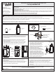
STEP 1 Adjust the Glass panels-
Remove the fixture from the package and check glass panels. If
there are any loosen glass panels, please refer to the follows to
make adjustment.
A. Remove the Cage from the Fixture by unscrewing Lock Screws.
B. Remove the Glass Panel Holder from the top of the Cage by
unlocking Hex Nuts.
C. Adjust Glass Panels to proper location and then secure with the
removed Glass Panel Holder. Hand tighten until with Hex Nuts.
D. Place Cage back onto Fixture and secure with Lock Screws.
Figure 1
Figure 3
Supply Wires with
Ground Wire
AA
Outlet Box Screws
(not included)
Outlet Box
STEP 3 - Attach Lanyard
A. The purpose of the lanyard is to provide
the installer a means to support the
fixture from the junction box while
connecting the electrical wires. This
enables the fixture to hang from the
junction box and your hands are free to
make the wire connections.
B. TurntheButtonStopsoitmaybe
inserted into the Inner Backplate slot.
Make sure the Button Stop is completely
inside the Inner Backplate. Slowly
release the fixture to make sure it is
supported by the Button Stop. Proceed
to the wiring steps in the next step. Once
you are complete with the wiring there is
nothing to do with Lanyard. The Lanyard
will push into the junction box when the
fixture is placed for final mounting.
B
Button
Stop
Lanyard
Inner
Backplate
Figure 2
Lock
Screw
Cage
Glass
Panel
Holder
Hex
Nut
Glass Panel
STEP 2 Install Inner Backplate-
A. Pass the supply wires through the existing hole on the Inner
Backplate (AA).
B. Inner BackplateAttach the (AA) to the Outlet Box with the head of
the Green Ground Screw facing you. Secure it with Outlet Box
Screws (not included). Tighten until snug.
STEP 4 - Wire Connections
A. Use standard wire connectors (not included) to make all wire
connections. (Connectors are not included with fixture.) Strip and
prepare wire ends according to instructions supplied with
connectors.
B. Connect White Supply Wire from the Outlet Box to Ribbed side Wire
from fixture.
C. Connect Black (or Red) Supply Wire from the Outlet Box to Smooth