
Installation Guide

2of3
2016 QuoizelInc.
Supply Wires
and Ground Wire
Thank you for purchasing a Quoizel product.
Need assistance with parts or assembly? Call Quoizel customer service at 1-800-645-3184
or visit us on-line at www.quoizel.com
A
HH
GG
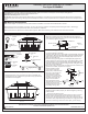
(Step 4 Continued)
Wires and the Ground Wire through the Ceiling Canopy (HH).
C. Attach one end of the Fixture Chain (GG) to the Fixture Loop (A)
on the top of the Fixture Body (B) with one Quick Link (FF). Lift the
fixture and Fixture Chain (GG) up and attach the other end of the
Fixture Chain (GG) onto the fixture loop on the bottom of the
Ceiling Canopy (HH) with another Quick Link (FF).
Suggested chain length for Ceiling height :
8’ ceiling : use 4 links of chain and 2 quick links
9’ ceiling : use 14 links of chain and 2 quick links
10’ ceiling : use 24 links of chain and 2 quick links
Figure 4
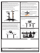
STEP 5 - Attach Lanyard
A. The purpose of the lanyard is to provide the installer a means to
support the fixture from the junction box while connecting the
electrical wires. This enables the fixture to hang from the junction
box and your hands are free to make the wire connections.
B. Turn the Button Stop so it may be inserted into the Crossbar slot.
Make sure the Button Stop is completely inside the Crossbar.
Slowly release the fixture to make sure it is supported by the Button
Stop. Proceed to the wiring steps in the next step. Once you are
complete with the wiring there is nothing to do with Lanyard. The
Lanyard will push into the junction box when the fixture is placed for
final mounting.
Crossbar
Button Stop
Lanyard
Slot
Figure 5
Figure 6
White wire
from supply
Ribbed side of wire from fixture
identified with the Label “N”
Black wire from
supply (or Red)
Smooth side of wire from fixture
identified with the label “L”
Ground wire
from supply
Ground wire
from fixture
STEP 6 - Wire Connections
A. Use standard wire connectors (not included) to make all wire
connections. Twist connectors until wires are tightly joined
together. Wrap each connection with approved electrical tape and
carefully stuff all the connected wires into outlet box.
Note: If the electrical wire is going to be cut shorter than provided
you will need to identify the "L" line wire and the "N" neutral wire
before you cut the excess wire off. One is labeled N and the other
labeled L. To do this separate the "L" line wire and the "N" neutral
wire as far as you need to. Re-label the wire near where you want to
make the cut. Be sure to mark the wire on the side of the fixture and
not on the excess wire being cut and removed.
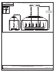
STEP 7 Install Ceiling Canopy to Ceiling-
A. Attach the Ceiling Canopy (HH) over the end of the Nipple (DD) and
secure with the Hex Nut (CC). Hand tighten until snug.
B. Thread the Lock Nut (EE) onto the end of the Nipple (DD) and hand
tighten until snug.
Figure 7
DD
Figure 8
Bulb (not
supplied)
Socket
FF
FF
HH
CC
EE
HH
STEP 8 - Install Bulbs
A. Optional Candle Covers (C) are available for this item. Replace the
existing candle covers with Optional Candle Covers (C).
B. Insert bulbs into sockets and screw snugly into place.
Your fixture is now assembled and ready to use. Enjoy!
C
ReleasedDate:2016-11-10