
Installation Sheet

1of2
For Style WVR1612A
Package Contents
Warnings and Cautions
Turn off electricity at circuit breaker or main fuse box before installation. Consult a licensed electrician if in doubt.
These instructions are provided for your safety. It is very important you read them completely before installing the fixture. We strongly
recommend that a licensed, professional electrician perform the installation.
Disconnect fixture from power source before replacing bulbs. Make sure bulbs are given sufficient time to cool before removal.
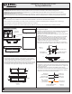
A
F
Crossbar
Assembly
x1
Pleasegoto forproductcleaningtips.Gotothe selection.
(2)B10CandelabraBasebulbs60WMaximum,CandelabraBaseT8Vintage Bulbs are recommended, bulbs not included..
20-30minutes
Identifyandinspectallpartsbeforebeginninginstallation.Checkpackagecontentlistanddiagramsbelowtoensureallpartsare
present.Ifanypartsaremissingordamaged,donotattempttoassemble,install,oroperatethefixture.Contactyouroriginalplaceofpurchase.
www.quoizel.com Care+Maintenance
LightSource:
EstimatedAssemblyTime:
Preparation:
ToolsRequired: Flathead screwdriver, Phillips screwdriver, pliers, wire cutters, wire strippers, electrical tape, safety glasses.
Installation Guide #IS-WVR1612A
C
Fixture Body
x1
B
Lock Screw
x2
2018 QuoizelInc.
ReleasedDate:2018-10-08
visit us on-line at www.quoizel.com
STEP 2 - Install the Crossbar Assembly to Outlet Box and Adjust
the length of the Nipple
A. Attach the Crossbar Assembly (A) to the Outlet Box with the head of
the Green Ground Screw facing you. Secure it with Outlet Box
Screws (not included), tighten until snug
B. Adjust the hex nut and lock washer underside of the crossbar to the
middle of the nipple.
C. Remove the mounting ball from the nipple. Place the Fixture Body
(C) over the nipple against the ceiling to determine the correct
position of the nipple. Thread the mounting ball onto the nipple.
Adjust the nipple to allow the Fixture Body (C) to rest against the
ceiling when held in place by the mounting ball.
D. Remove the mounting ball and the Fixture Body (C). Tighten the
lock washer and the hex nut against the crossbar to secure in place.
.
Cage
x1
Hex Nut and
Lock Washer
Nipple
Green Ground Screw
Outlet Box Screw
(not included)
Mounting Ball
Figure 2
D
Square Glass Panel
x1
E
Side Glass Panel
x4
STEP 1 Install Glass Panels-
A. Place the Square Glass Panel (F) into the bottom of the Cage (D)
with the beveled edge on the bottom. Secure by pressing tabs in the
bottom edge of the Cage (D) to the Square Glass Panel (F).
B. Place Side Glass Panel (E) between the Square Glass Panel (F) and
the Cage (D) with beveled edge outside. Secure by pressing tabs on
the top edge of the Cage (D) to top edge of Side Glass Panel (E).
E
F
D
Tab
Tab
Figure 1
A
C
STEP 3 - Wire Connections
A. Wrap bare or green ground wire around green ground screw on the
crossbar, no less than 2 inches from the end of the wire. Tighten the
green ground screw.
B. Use standard wire connectors (not included) to make all wire
connections. Twist connectors until wires are tightly joined together.
Wrap each connection with approved electrical tape and carefully
stuff all the connected wires into the Outlet Box.
Green Ground Screw
on the Crossbar
White wire
from outlet box
White wire
from fixture
Black wire from
outlet box (or Red)
Black wire
from fixture
Bare, or Green
Ground wire
from outlet box
Ground wire
from Fixture
Figure 3