
Specifications


15CG-PRC007-EN
LonTalk Chiller Communication Module
— LonTalk is a communications protocol
developed by the Echelon Corporation.
The LonMark association develops control
profiles using the LonTalk communication
protocol. LonTalk is a unit level protocol,
unlike BACNet used at the system level.
LonTalk Communications Interface for
Chillers (LCI-C) provides a generic
automation system with the LonMark
chiller profile inputs/outputs. In addition to
the standard points, Trane provides other
commonly used network output variables
for greater interoperability with any
automation system.
Additional ouputs:
Evaporator Water Pump Request
Evaporator Refrigerant Temperature
Evaporator Refrigerant Pressure
Condenser Refrigerant Temperature
Condenser Refrigerant Pressure
Outdoor Air Temperature
Condenser Air Flow
Condenser Fan Status
Compressor Running
Maximum Capacity Status
Hot Gas Bypass
Current Per Line
Trane controls or another vendor’s system
can use these points with ease to give the
operator a complete picture of how the
system is performing.
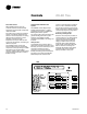
Generic Building Automation System
Module (GBAS) — Two Generic Building
Automation System modules (GBAS) are
available as an option to provide broad
control capabilities for building
automation systems, other than Trane’s
Tracer system.
The 0-5 vdc input GBAS Module contains
4 analog inputs, one binary input for
demand limit, and 5 binary outputs.
The 4 analog inputs can accept a 0-5 vdc or
a three wire potentiometer signal and be
assigned to:
1. Leaving Solution Set point
2. Ice Build Terminate Set point
3. Hot Start Load Limit Set point
4. Maximum Capacity Level
Set point
The 5 binary outputs can be assigned:
1. Active Unit Diagnostics
2. Compressor running status
3. Maximum Capacity (all
compressors running)
4,5.Open - Diagnostics can be
grouped or individually assigned
by the user and may be placed
in these outputs.
The 0-10 vdc input GBAS module
contains 4 analog inputs, one binary
input for demand limit, four analog
outputs and one binary output.
The 4 analog inputs can accept a 0-10 vdc
signal and be assigned to:
1. Leaving Solution Set point
2. Ice Build Terminate Set point
3. Hot Start Load Limit Set point
4. Maximum Capacity Level Set point
The 4 analog outputs can be assigned to:
1. Leaving Solution Temperature
2. Entering Solution Temperature
3. Saturated Condenser Temp.
Ckt 1, 2
4. Evaporator Temp. Ckt 1, 2
5. Liquid Line Pressure Ckt1, 2
6. Suction Pressure Ckt 1, 2
7. Actual Capacity Level
8. Outdoor Air Temperature
One binary output can be assigned to:
1. Active Unit Diagnostics
2. Compressors Running Status
3. Max Capacity
Alarm and Max Capacity Relay — These
features are user selectable and are
mutually exclusive of each other. If the
alarm relay output is selected, it will
provide a way to trigger a field supplied
alarm whenever the UCM detects a fault
requiring manual reset. The customer
can assign which fault modes will trigger
the alarm relay. The alarm will
de-energize when the manual reset is
cleared. When Max Capacity Output is
selected, it will trigger a field installed
device indicating the unit has reached its
maximum cooling stage; this gives the
customer the ability to turn on auxiliary
systems to manage comfort.
Hot Gas Bypass (HGBP) — The HGBP
control allows unit operation below the
minimum step of unloading. Hot gas
bypass is initiated when the last capacity
step is running and the capacity control
algorithm generates a subtract
command. HGBP remains energized until
the load increases, the chiller freeze
protection function is activated, a user
defined run time has expired, the low
pressure control is open, or the unit goes
into ice building mode.
Ice Building Control — A contact closure
on the UCM allows either a field installed
device or an ICS system to initiate the
unit to operate in the ice building mode.
In this mode normal chiller temperature
control is bypassed and the unit runs
fully loaded until ice building is
complete. There are two optional ice
building modes that can be selected
through the HI. Ice building is
terminated when the customer provide
contacts are opened, Ice Building Stop is
initiated from Tracer, or the entering
solution temperature reaches or drops
below the ice building terminate set
point.
Option 1 - One time Ice building mode
allows the unit to run fully loaded until
the entering solution temperature falls to
the active ice building terminate set
point (IBTS) When the entering solution
temperature reaches the terminate set
point, the unit will go through
pumpdown if enabled and remain in Ice
Complete standby mode until the ice
build mode is terminated.
Option 2 - Continuous ice build mode
allows the unit to run fully loaded until the
entering solution temperature falls to the
active ice building terminate set point
(IBTS). When the entering solution
temperature reaches the terminate set
point, the unit will go through pumpdown
if enabled, and remain in Ice build delay.
The unit will remain in ice build standby
until the ice build timer expires. The unit
will then start the pump and wait for the
loop stabilization timer to expire. The unit
will run fully loaded until the entering
solution temperature falls below the ice
build termination set point. The unit will
continue cycling through these ice
building states until the Ice build mode is
terminated or changed to option 1.
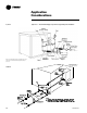
20–60 Ton
InterfaceControls