
User's Manual
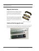
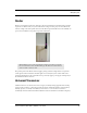
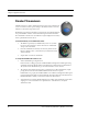
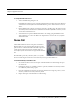
Table Of Contents
- Federal Communication Commission (FCC) Compliance
- Industry Canada Compliance
- Overview
- Intended Audience
- Additional Detailed Documentation
- Contact Information
- Product Warranty
- Chapter 1
- Introduction
- Central Server and Client Computers
- 9450 System
- Exit Alarm Controller
- Card Reader Access Device
- The Exit Alarm Zone
- Exit Alarm Receiver
- Magnetic Reed Switch
- CodeLock Electromagnetic Lock
- Alarming Band Receivers
- Alarming Band Zone
- Quick Look Display
- Transmitters
- Wander Management Transmitter
- Alarming Band Transmitters
- Mother Transmitter
- 9600 QR System
- Gateway
- Router
- Universal Transceiver
- Pendant Transceivers
- Pull-Cords
- Check-in Pull Cord
- Nurse Call
- Smoke Detector
- Asset Transceiver
- Door/Window Transceivers
- Reset Button
- Fall Management Systems
- Sensor Pads
- Using the Fall Management System
- Pagers and Walkie-Talkies
- Event Paging
- Pager Delays, Retries and Escalation
- Walkie-Talkie System
- Chapter 2
- Introductions
- Start the Software
- Window Conventions
- Touchscreen Monitor
- Map Orientation
- Ruleset for Displaying Patient Name
- The Main Window
- The Menu Bar
- Monitor
- Tools
- Paging
- Asset
- Help
- Top Toolbar
- Bottom Toolbar
- Low Battery Icon
- Chapter 3
- Introduction
- Commonly Used Terms
- Login and Passwords
- Units
- Supervised Transmitters
- Global Lockdown
- Common Operations
- Admit
- Patient Admit Information Window
- Asset Admit Information Window
- Discharge
- Escort
- Transfer
- Adjust
- Reports
- Silence
- Chapter 4
- Introduction
- Events
- Devices Displayed on the Map
- Devices Assigned to a Room
- Event Types
- Event Information Window
- Event Information Window Properties
- Red Alarms
- Door Alarm
- Exit Alarm (Wide Gap)
- Smoke Alarm
- Perimeter Alarm
- Cut Band Alarm
- Mismatch Alarm
- Match Alarm
- Link Alarm
- Check Alarm
- Check Transmitter Alarm
- Assistance Required
- Server Missing
- Yellow Alarms
- Client Missing
- Device Fault
- Low Battery
- Blue Alarms
- Door Alarm
- Cut Band Alarm
- Check Transmitter Alarm
- White and Light Blue Alarms
- Auto-enroll (White Alarm only)
- Escort to Expire
- Escort Expired
- Transfer to Expire
- Transfer Expired
- Discharge Expired
- Adjust Expired (White Alarm only)
- Begin Adjust (White Alarm only)
- Admit Complete
- Discharge Complete
- Escort Complete
- Transfer Complete
- Adjust Compete (White Alarm only)
- Chapter 5
- Introduction
- Reports
- Viewing a Report
- Reports Toolbar
- System Reports
- Response Time
- Activities Report
- Alarm Report
- Alarm Response Report
- All Activities Report
- JCAHO Report
- JCAHO Assistance Report
- Alarm Activities Report
- Census Report
- Auto Enrolled History Report
- Adjusted Bands Report
- Transfer Report
- Escort Report
- Discharge Report
- Staff Drill Report
- System Maintenance Report
- Low Batteries Report
- Device Fault Report
- Device Hardware Report
- Transmitter Report
- Users Report
- Training Report
- User Training Report
- All Other Reasons Report
- Links Report
- Links Activities Report
- Patient Reports
- Review Info Report
- Review Activity Report
- Review Response Report
- Asset Reports
- Asset Transmitter Report
- Asset Activities Report

Series 5.0 Software (0510-1059-A_DRAFT) - User Guide 9
9450 System
Alarming Band Receivers
Alarming Band Receivers are placed strategically throughout the monitoring area to receive signals from the
alarming band transmitters worn by patients. If the Cut Band feature is enabled, the system alerts staff if the
banding material that holds the transmitter to the patient is tampered with, cut, or opened without authorization.
Multiple receivers are used to ensure reception of the signal if there is an effort made to shield the transmitter
during abduction or elopement attempts. For more information, see the Alarming Band Receiver Installation
Guide.
Alarming Band Zone
An Alarming Band Zone is the area within range of an Alarming Band Receiver, several of which are mounted
above the ceiling tiles of a facility. If a Cut Band alarm is triggered in an Alarming Band Zone, an alarm is sounded
on all Client computers assigned to monitor transmitter’s unit, a message is displayed in the Event List, and the
location of the Alarming Band Receiver that detected the event is indicated on the map on the Client
computer(s).
Quick Look Display
The Quick Look Display shows information from the system at both a central and
remote location such as a secondary nurse’s station. When an alarm is issued from the
system, it is received through the Quick Look Interface. The type of alarm (Cut Band,
Door, Check), location of the alarm and the transmitter ID are displayed on a large,
easy-to-read 2 x 20 Character Vacuum Fluorescent Displays (VFDs). As new alarms
occur, they appear immediately; the display then begins scrolling through each active
alarm. For more information about the Quick Look Display, see the Quick Look
Display and Interface Installation Guide.
NOTE: The Mother/Infant function requires applicable Alarm Band Receivers.